3522.5-0000010 РЭ
124
3.6.11 Check and adjustment of axial clearance in bearings of cage of back
rest for drive gear-shaft of the master pair
The axial clearance in the bearings shall not exceed 0,1 mm. The adjustment shall be
carried out by means of changing the number of shims 2 (figure 3.6.6). When carrying out ad-
justment turn the cage 3 to make rollers take their position in the cage. Assembly and adjust-
ment shall be carried out before mounting the cage 3 ready-assembled on the plate 1.
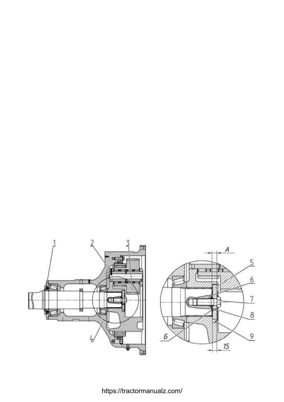
3.6.12 Check and adjustment of axial clearance in axle shaft bearings
The axial clearance in the axle shaft bearings shall not exceed 0,1 mm. The ad-
justment shall be carried out by means of changing the number of shims 8 (figure 3.6.8)
between an axle shaft 6 and a washer 5. To carry out adjustment it is needed to take a
lock washer 9 out from the carrier, unscrew bolt 7 out of the axle shaft and remove the car-
rier 2 ready-assembled from splines of the axle shaft 6. Hereby the washer 5 remains in
the carrier in a non-fixed position.
If the adjustment is carried out after replacement of one or two bearings of the axle
shaft, the estimated thickness of a set of shims 8 is defined by means of deducting the
washer thickness equal to 15 mm from a dimension “A” (between the end of the axle shaft
6 and an outer end of the washer 5), measured with a beam-compass through an orifice
“Б”. The shims 8 shall not be mounted when measuring the dimension “A”.
When carrying out adjustment it is required to turn the axle shaft so that the rollers
took their position in the bearings. The adjustment is performed without the cover with
gland 1. After adjustment the axle shaft shall turn with small resistance (from 20 to 30 N×m)
without seizure and jamming.
ATTENTION:
- MOUNTING THE CARRIER 2 (FIGURE 3.6.8) READY-ASSEMBLED WITH
DOUBLE-RIM SATELLITE GEARS 3 INTO THE TUBE 4, SET THE MARKED TEETH
ROOTS OF THE BIGGER RIMS (Z=42) OF DOUBLE-RIM SATELLITES 3, ON LINES
PASSING THROUGH THE SATELLITE GEAR CENTER AXES AS WELL AS THROUGH
THE CARRIER AXIS!
- THE FINAL TIGHTENING TORQUE FOR BOLT 7 OF THE AXLE SHAFT WITH
SHIMS MOUNTED IS 650 TO 700 N·M!
- TO BRING THE NIB THE LOCK WASHER 9 INTO COINCIDENCE WITH CAVI-
TIES IN THE CARRIER 2 IT IS NOT ALLOWED TO UNSCREW THE BOLT 7 OF THE
AXLE SHAFT!
1 – cover with gland; 2 – carrier; 3 – double-rim satellite gears; 4 – tube; 5 – axle
shaft washer; 6 – axle shaft; 7 – axle shaft bolt; 8 – shims; 9 – lock washer.
Figure 3.6.8 – Final drive
https://tractormanualz.com/

 Loading...


