3522.5-0000010 РЭ
27
To the figure 2.1.1 – Layout of controls and instruments of the tractor:
1 – sun visor; 2 – cab light with switch; 3 – place for radio receiver (car stereo) installa-
tion; 4 – conditioner control panel; 5 – upper shield unit of button switches; 6 – deflectors; 7
– recirculation shutters; 8 – supplementary switch of rear screen wiper; 9 – accumulator bat-
tery remote disconnect switch; 10 – starter and instruments switch; 11 – left multifunctional
underwheel switch; 12 – steering wheel; 13 – instrument board; 14 – pilot lamps unit; 15 –
integrated indicator; 16 – integrated indicator control panel; 17 – right multifunctional under-
wheel switch; 18 – emergency flashing switch; 19 – central light switch; 20 – switch of front
working lights mounted on front lights brackets; 21 – information display; 22 – parking brake
control lever; 23 – clutch control pedal; 24 – handle for steering rake fixation; 25 – left brake
control pedal; 26 – right brake control pedal; 27 – accelerator pedal; 28 – handle for fuel
supply control; 29 – range shifting lever; 30 – reduction gear control unit; 31 – rear lift link-
age control console; 32 – integrated electronic control system; 33 – module for programming
rear lift linkage operations; 34 – combined electronic panel; 35 – electronic joystick unit; 36 –
console of front lift linkage control; 37 – gear shifting joystick;
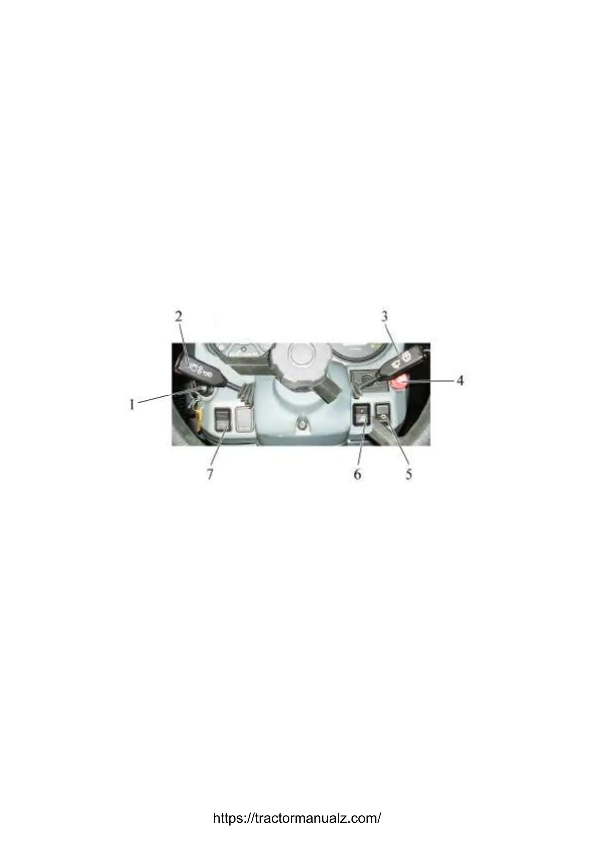
2.2 Switches of instrument board
1 – starter and instruments disconnect switch; 2 – left multifunctional underwheel
switch; 3 – right multifunctional underwheel switch; 4 – emergency flashing switch; 5 – cen-
tral light switch; 6 – switch of front working lights mounted on front lights brackets; 7 – ac-
cumulator battery remote disconnect switch.
Figure 2.2.1 – Switches of instrument board
The starter and instruments disconnect switch 1 (see fig. 2.2.1) has four positions:
- «0» – off;
- «I» – instruments; pilot lamps unit, inlet air preheater are on;
- «II» – starter is on (non-fixed position);
- «III» – radio set is on.
The layout of positions of starter and instruments disconnect switch is given in fig.
2.2.2 and in informational plate of the switch.
https://tractormanualz.com/

 Loading...


