3522.5-0000010 РЭ
198
3.24 Cab air conditioning and heating system
The cab air conditioning and heating system is intended for development and keep-
ing of normal microclimate in the tractor cab. The air conditioning system consists of two
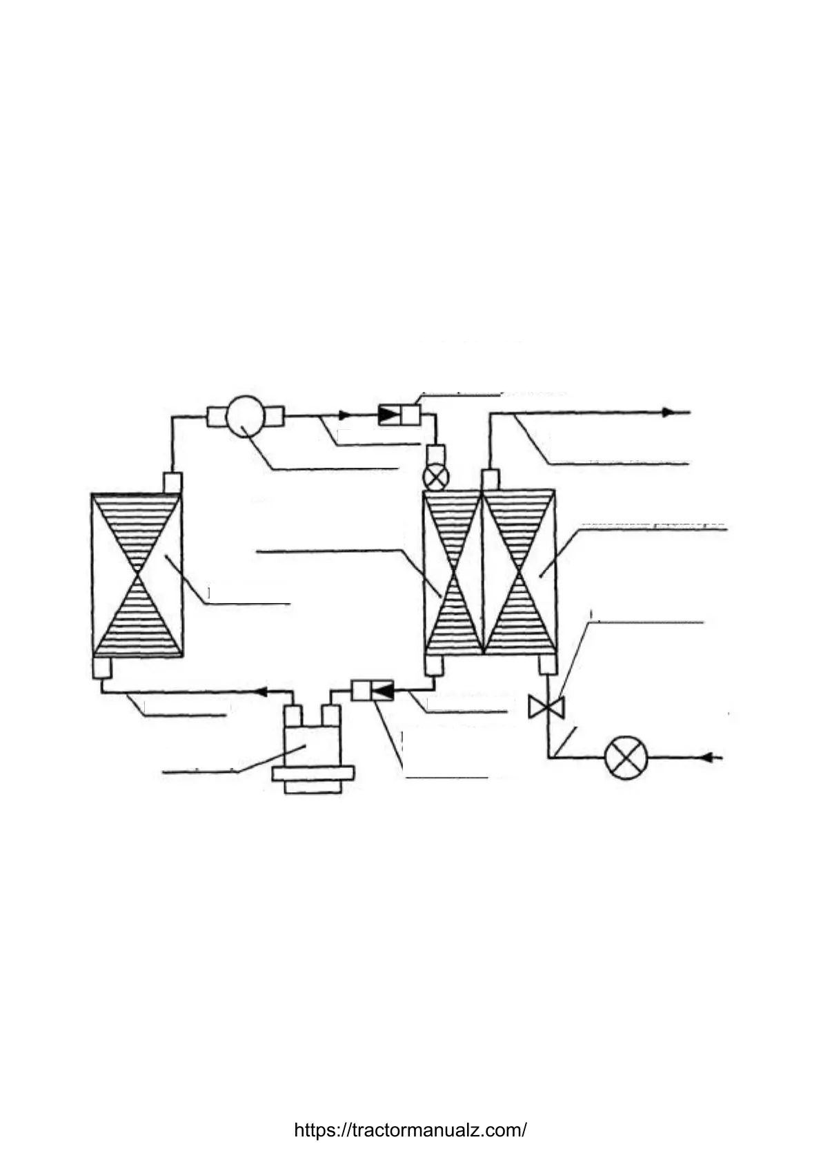
circuits – heating and cooling. The system diagram is shown in figure 3.24.1.
The cooling circuit include compressor, condenser, filter-drain with pressure sensor,
monobloque of evaporator and of heater radiator (heater/cooler), heater/cooler fan, con-
necting hoses with quick-couplings set, electric cables, air filters, regulator of cold air and
fan switch. The heating circuit is amended by horses, connected with engine cooling sys-
tem of the tractor and with shut-off valve.
Figure 3.24.1 – Cab air conditioning and heating system
The compressor 7 (figure 3.24.2) is located on the left at the bottom part of the engine,
condenser 8 is in front of CAC radiator, filter-drain 1 is on condenser frame, pressure sen-
sor is on filter-drain 1, heater-cooler 5 is under the roof above ventilation box panel, regu-
lator of cold air and fan switch is located on upper box panel , service valves are on fittings
near to the compressor 7 and filter-drain 1.
etween cab and filter-drain
cooling system
Filter-drain
cooling system
Compressor
Condenser
horses be
compressor
Heater valve
radiators monobloque
(cooling section of
https://tractormanualz.com/

 Loading...


