3522.5-0000010 РЭ
35
2.7 Integrated indicator and integrated indicator control panel
2.7.1 General information
The integrated indicator 15 (figure 2.1.1) (hereinafter II) and the integrated indicator
control panel 16 (figure 2.1.1) (hereinafter IICP) display information on operational pa-
rameters of systems and units of the tractor and provide operator with data on violation of
work or breakdown of any system.
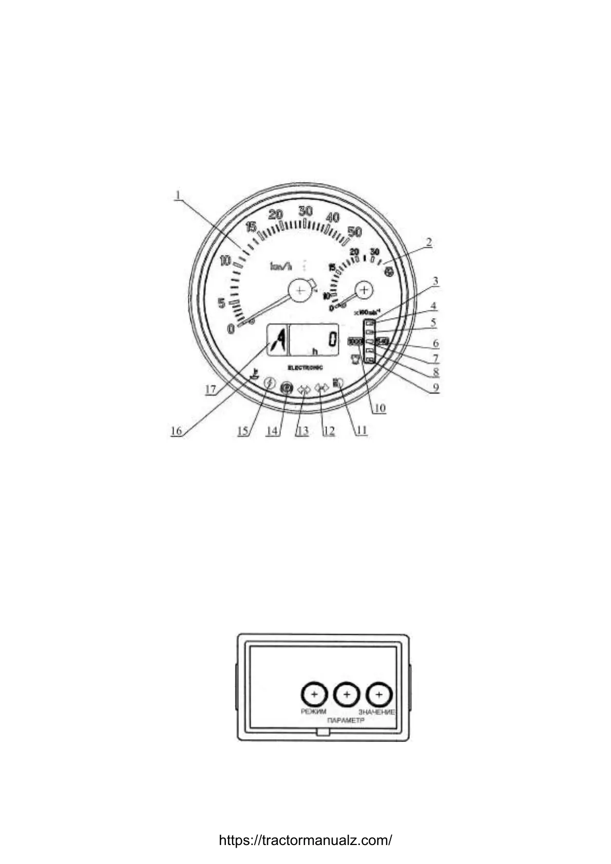
The II includes gauges and signal lamps as per figure 2.7.1.
1 – velocity gauge (needle indicator); 2 – engine speed gauge (needle indicator); 3
– rear PTO speed gauge (light indicator); 4, 9 – segments of rear PTO speed scale (yel-
low color); 5, 7, 8 – segments of rear PTO speed scale (green color); 6 – annunciator of
“540 min
-1
” of rear PTO speed scale range (yellow color); 10 – annunciator of “1000 min
-
1
” of rear PTO speed scale range (yellow color); 11 – pilot lamp to indicate headlights up-
per beam switching (blue color); 12 – pilot lamp to indicate switching of trailer turn blinkers
(green color); 13 – pilot lamp to indicate switching of tractor turn blinkers (green color); 14
– pilot lamp to indicate parking brake engagement (red color); 15 – pilot lamp to indicate
enhanced voltage in on-board system (red color); 16 – pilot lamp to indicate low level of
coolant (yellow color); 17 – multifunction display.
Figure 2.7.1 – Integrated indicator
The II control panel is presented in figure 2.7.2.
Figure 2.7.2 – The integrated indicator control panel
The control panel 16 (figure 2.1.1) allows to carry out manual programming with but-
tons «Параметр» (“Parameter”) and «Значение» (“Value”) (see figure 2.7.2), and also to
https://tractormanualz.com/

 Loading...


