3522.5-0000010 РЭ
177
3.16.5.2 Installation and adjustment of FLL position sensor
As far as front lift linkage with position control doesn’t have positive down movement,
it is better to load front lift linkage additionally with weight 150…2500 kg for convenience by
position sensor adjustment.
Installation and then adjustment of FLL position sensor should be made in the fol-
lowing order:
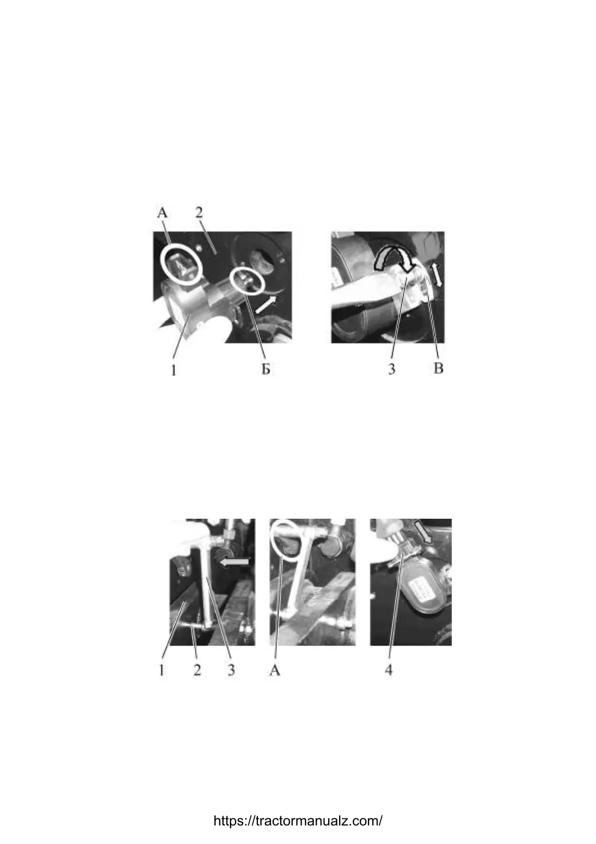
1. Install position sensor 1 (figure 3.16.13) in FLL bracket 2 in such way, that elec-
tronic connector “A” and marking (don’t change with hole) on sensor 1 shaft end “Б” are
directed at top. Screw two screws 3 (one at each side) through adjusting grooves in sensor
1 legs so that this screw could rotate freely within groove.
1 – position sensor; 2 – FLL bracket ; 3 – screw.
Figure 3.16.13 – Installation of FLL position sensor
2. Mount long lever of control mechanism 3 (figure 3.16.14) on axle 2, situated in
holes of draft link unit 1, move control mechanism to sensor shaft end (point A in figure
3.16.14). Then turning by screwdriver shaft end of position sensor (or position sensor it-
self) by small angles match hole in shaft end of position sensor with hole in lever and fas-
ten by cotter pin. Put harness connector 4 on sensor clamp. Set position sensor in such a
way that screws 3 (figure 3.16.13) are in the middle of the grooves.
1 – draft link unit; 2 – axle; 3 –control mechanism lever; 4 – electric wiring harness
connector of FLL control.
Figure 3.16.14 – Connection of control mechanism to FLL position sensor.
https://tractormanualz.com/

 Loading...


