3522.5-0000010 РЭ
165
Reverse valve switch 4 (figure 3.15.1) is installed for the purpose of HSC operation as
well as by forward motion of the tractor and by reverse motion. Reverse valve 4 is mounted to
the left under the hood at driver's cab on the left post of hood fixation bracket. The reverse
valve 4 is controlled by shifting the handle into one of two positions until it gets fixed in one
of them.
As oil reservoir serve general oil tank of HLL and HSC systems with 25 microns fil-
ter for working liquid clearing. In the system is installed the valve 6 which ensure operation
of HSC emergency oil pressure sensor.
The dosing pumps 2 and 3 are mounted on steering columns, hydraulic rotation
cylinders 1 are mounted on the front driving axle of the tractor, feed pump 5 is mounted
on the engine. The dosing pumps 2 and 3 are connected by oil lines with chambers of hy-
draulic rotation cylinders, with feed pump and oil tank. At linear movement the chambers of
cylinder 1 are locked by spool lands of dosing pump 2 or 3 and oil from feed pump 5 arriv-
ing to the dosing pump 2 or 3 comes back into oil tank. At steering wheel turn slider valve
of dosing pump 2 or 3 shifts and oil comes into one of chambers of hydraulic rotation cyl-
inder 1 in amount that correspond to the turn angle of steering wheel. Oil from the other
chamber of hydraulic cylinder 1 comes back through dosing pump 2 or 3 in oil tank.
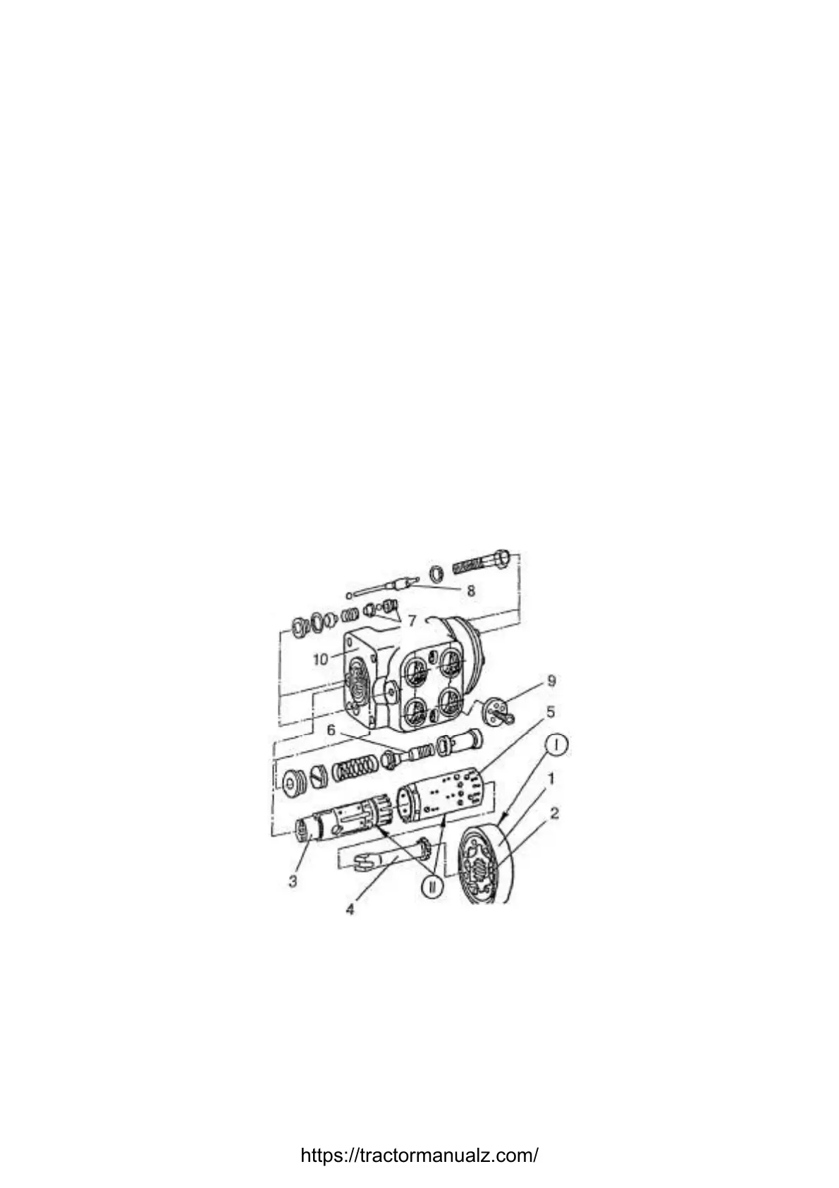
3.15.2 Dosing pump
The dosing pumps of forward and reverse motion are gerotor type pumps with
¨open center¨ and with no reaction to steering wheel. The dosing pump include tilting unit I
(figure 3.15.2), distributor II, return valve 9, two anti-shock valves 7, protection valve 6 and
two air-inlet valves 8.
The dosing pump of reverse motion is single-capacity pump and is shown in figure
3.15.2.
1 – stator; 2 – rotor; 3 – slide valve; 4 –driven shaft; 5 – liner; 6 – protection valve; 7 –
anti-shock valves; 8 – air-inlet valves; 9 – return valve; 10 – casing. I – tilting unit; II –
distributor
Figure 3.15.2 – Single capacity dosing pump
Gerotor tilt unit I (figure 3.15.2) consist of stator 1, which is fixed on casing 10, and
of rotating rotor 2 connected with slide valve 3 through driven shaft 4. The distributor II
consists of casing 10, liner 5 and sliding valve 3 connected by splines with driven shaft end
extension of steering column.
https://tractormanualz.com/

 Loading...


