3522.5-0000010 OM
250
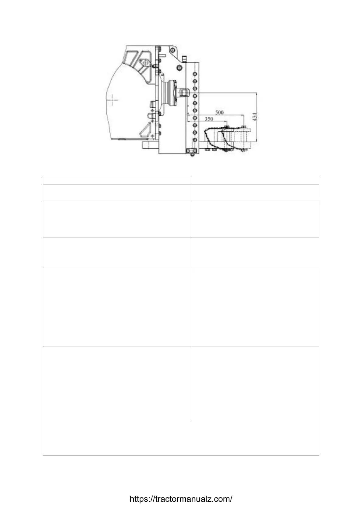
5.4.3. Drawbar hitch “Draw bar”
Figure 5.4.3 – Installation variants scheme of “Draw bar”
Table 5.5 – Basic parameters и coupling dimensions of “Draw bar”
Standard size (configuration) of the device Draw bar
1 Mounting location At the bottom of rear axis body and rear
lifting device
2 Design features Towing yoke, nonrotational, located on a
longitudinal beam blocked against tractor
frame, with possibility to set the hitch
point in two points against PTO
end butt
3 Purpose For connection and coupling of trailed
semitrailed implements with traveling
wheels excluding tractor trailers and
semitrailers
50
4 DH hook dimensions, mm:
а) connecting pin diameter
b) towing yoke gap height
c) towing yoke gap width from a bolt
90
R90
d) distance between towing yoke gap in
vertical position and ground contact area, mm 541
e) towing yoke position
1)
for the implement
driven by rear PTO shaft
Unchangeable
2)
f) distance between PTO shaft end and
connection pin axis
350, 500
5 Trailing appliance for connection to DH:
а) type Rigid, with tractor drawbar clevis
b) vertical load in hitch point, kN, not
than
30 (for 350), 21 (for 500)
c) trailing appliance steering angle in hori-
zontal plane, degrees, not less than
±65
d) protective mean type
Safety chain (rope)
2)
e) connection point of a
of the tractor
Lifting device bore
_____________________________________________________________________________________________
1)
Recommended.
2)
It is not allowed to locate a pad on the bottom of the draw bar (with overturn)
lower the towing yoke against ground contact area.
3)
Implement accessories.
https://tractormanualz.com/

 Loading...


