3522.5-0000010 РЭ
134
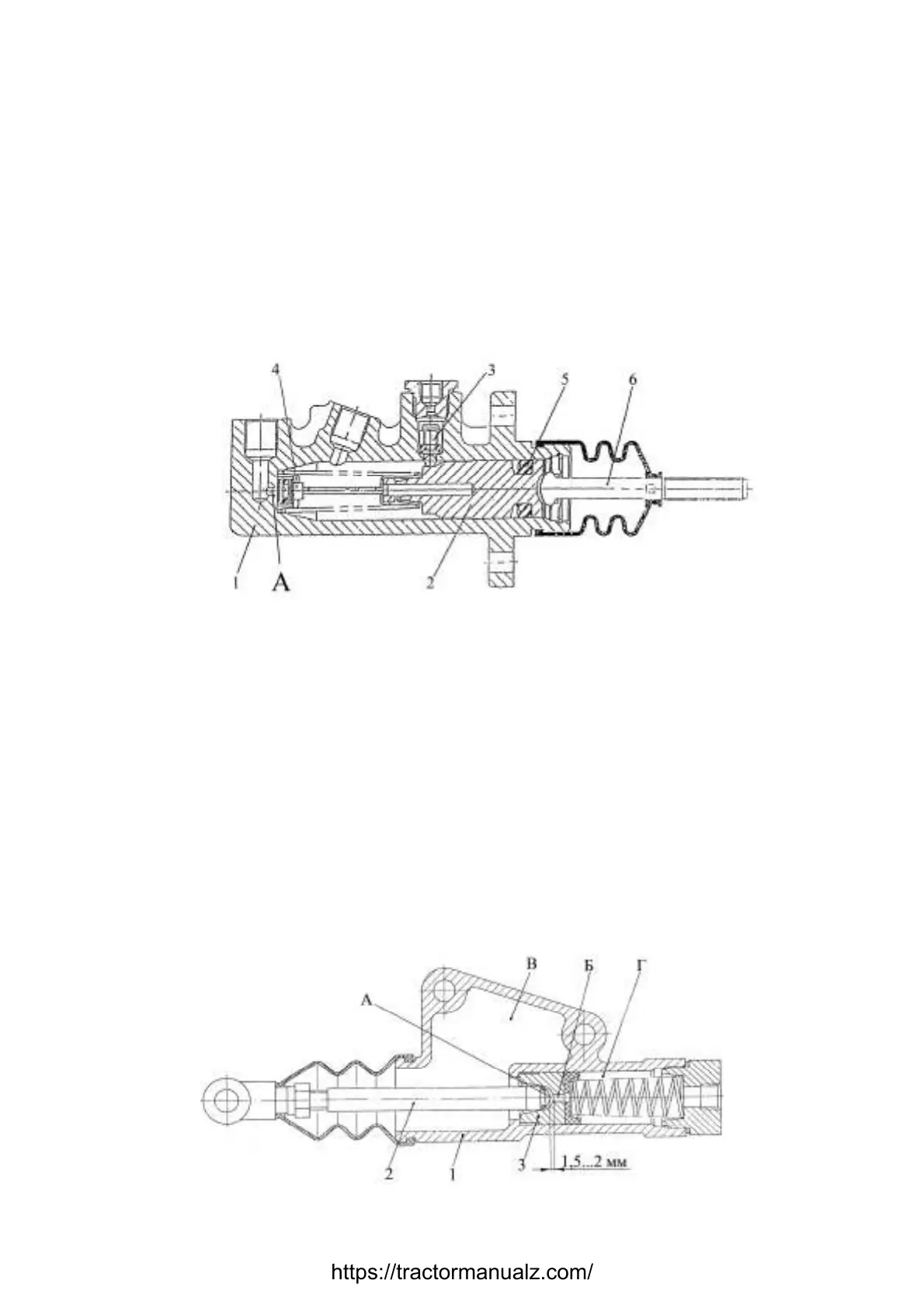
3.9.5 Brake Operation with Forward Pedal Drive
When pressed on brake pedal, the push rod 6 (figure 3.9.6) of main brake cylinder con-
nected with pedal lever moves forward. Meanwhile is closed the lock valve 4 through which in
casing 1 arrives brake fluid from tank. The piston 2 moves forward, pushing compensation
valve 3. The power fluid is pumped under pressure into operating cylinder of brake.
The piston of operating cylinder moves under pressure of power fluid and through a
slide bar connected to lever 23 (figure 3.9.4) by means of a pin 15 turns lever 23, this lever
bearings against the bolt 9, lifts lever 16 connected through spherical washer 7, fixed by
nuts 22 and 8 on rod 14, lifts this rod, tightening brake by pressure disks. When there is no
force on pedal, the spring 11 resets lever 16 and piston of operating cylinder 12 in starting
position.
When pressed on interconnected pedals, the compensation valves 3 of main brake
cylinders ensure fluid pressure balance in lines of left and right brake operating cylinders.
1 – casing; 2 – piston; 3 – compensation valve; 4 – lock valve; 5 – collar; 6 – push
rod.
Figure 3.9.6 – Main brake cylinder
3.9.6 Brake Operation with Reverse Pedal Drive
When pressed on brake pedal, the push rod of main brake cylinder 2 for reverse
(figure 3.9.7), connected with pedal lever, moves. Meanwhile is closed the hole “Б” con-
necting balance chamber "В" with chamber “Г”. The piston 3 moves creating pressure.
Then power fluid is pumped under pressure into operating cylinder for reverse.The piston
of operating cylinder for reverse thanks to pressure of fluid moves and through a rod con-
nected with lever 32 (figure 3.9.2) by means of a pin 23 turns brakes shaft 20 (figure 3.9.4),
which influences through intermediate rods 5 brakes drive mechanisms for forward motion,
tightening brake by pressure disks.
1 – casing; 2 – push rod; 3 – piston.
Figure 3.9.7 – Main brake cylinder for reverse
https://tractormanualz.com/

 Loading...


