3522.5-0000010 РЭ
142
3.11 Transmission Hydraulic System
3.11.1 General information
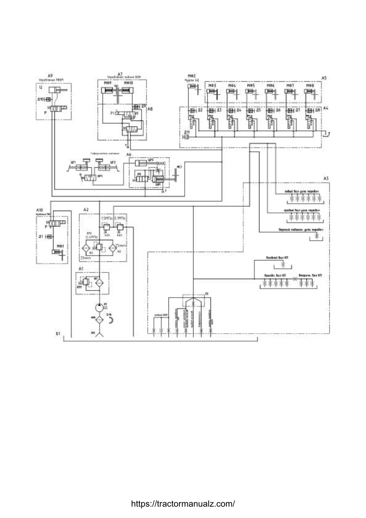
Hydraulic circuit diagram is shown in figure 3.11.1.
А1 –mesh filter; А2 – duplex filter; А3 – oil unit; А4 – electrohydraulic distributor; А5 – gear
shift group; А6 –assembled coupling hydraulic booster; А7 –rear PTO control; А8 –
hydraulic distributor; А9 –front PTO control; А10 – FDA (front driving axle) control; Б1 –
transmission case; Д1 … Д10 – pressure sensors; Д11 – pressure sensor; КД1 –control
valve; КД2 – lubrication valve; КП1, КП2 –safety valves; КР1 – forward and reverse motion
selector valve; МЗ –suction bell; МС1 –coupling clutch; МФ – magnetic filter; МФ1 –FDA
clutch; МФ2 –differential lock clutch; МФ3 … МФ8 – GB gear activation clutch; МФ9 –
PTO brake actuating clutch, МФ10 – PTO friction engagement clutch, Н1 –gear wheel
pump НШ25; П1 –distributor plate; Р – distributor; Р1 … Р8 –proportional valve; Р9–
valve; Ф1 – mesh filter element; Ф2 – paper filter element; Ц – cylinder; ЦГ1 – the cylinder
main on direct to a course; ЦГ2 –main cylinder for forward motion; ЦР3 – operating cylin-
der; ЦИ1 – hydraulic booster cylinder.
Figure 3.11.1 – Transmission hydraulic circuit diagram
https://tractormanualz.com/

 Loading...


