6-14
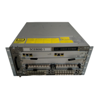
Cisco SCE8000 GBE Installation and Configuration Guide
Chapter 6 Cabling the Line Ports and Completing the Installation
Cabling the 10 GBE Line Interface Ports: Using the External Optical Bypass Module
Cabling the 10 GBE Line Interface Ports: Using the External Optical Bypass
Module
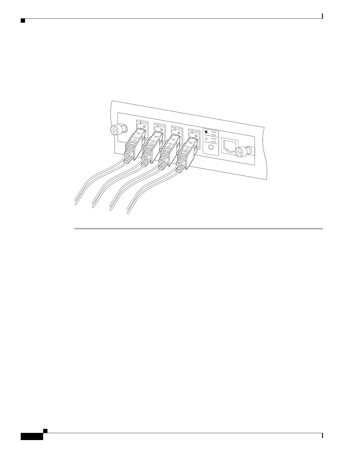
See Optical Bypass Module Connectivity, page 6-9 for specific connectivity (Figure 6-2).
Figure 6-2 External Optical Bypass Module Line Interfaces
Step 1 Take the appropriate fiber optic cable (see XFP Module Cabling and Connection Equipment, page 6-11)
and plug it into the appropriate port (A or B) on the external bypass module.
Step 2 Using a cable with LC connectors on both ends, plug one end into the appropriate port (C or D) on the
external bypass module and the other end into the appropriate 10 GBE interface in slot 3 of the
Cisco SCE 8000 chassis.
270978
TX
R
X
A
TX
RX
B
TX
RX
C
TX
RX
D
A
B
A
C
C
D
B
D
STAT
U
S
CTRL
OPB—SCE8K—MM
 Loading...