2-15
Cisco SCE8000 GBE Installation and Configuration Guide
Chapter 2 Introduction to the Cisco SCE 8000 10 GBE Platform
Fan Assembly
Optical Bypass Module Specifications
This section describes the following:
Fiber Cable Type
The fiber cable type within the Optical Bypass Module area as follows:
• OPB-SCE8K-MM: 50 um core
• OPB-SCE8K-SM: SMF-28
Maximum optical path (fiber length of two ports) is 600 m.
Switching Time
Switching time is measured from trigger to stable 90% optical output.
• Typical switching time: 3 ms
• Maximal switching time: 10 ms
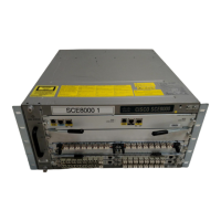
Fan Assembly
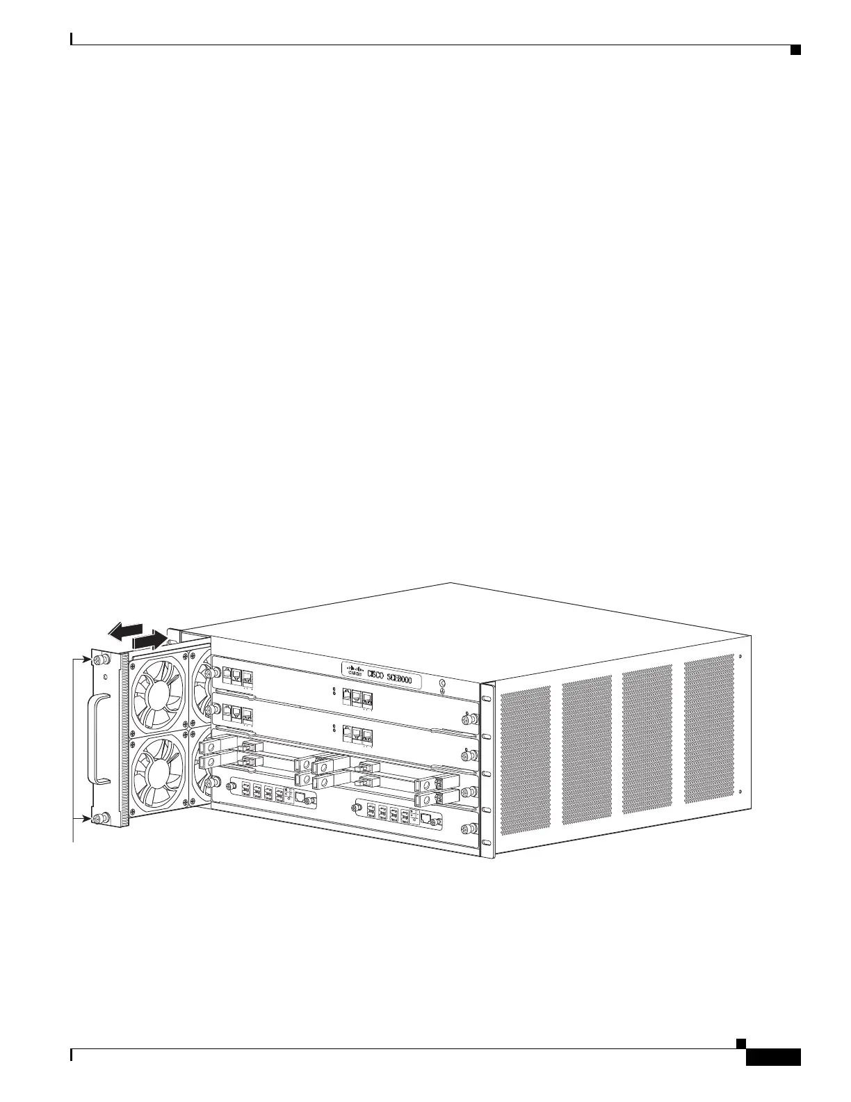
The system fan assembly, located in the chassis, provides cooling air for the installed modules (See
Figure 2-9). Sensors on the fan assembly and within the system monitor the internal air temperatures. If
the air temperature exceeds a preset threshold, the environmental monitor displays warning messages.
Figure 2-9 Fan Assembly
If an individual fan within the assembly fails, the FAN STATUS LED turns red. To replace a fan
assembly, see “Removing and Replacing the Fan Assembly” section on page 9-13.
270893
S
YSTE
M
POW
ER
O
P
T
I
C
AL BY
P
A
S
S
S
TA
TU
S
A
UX
POR
T
2
LINK
AC
T
IVE
M
AS
T
E
R
SC
E8
0
00
E
X
T
E
N
D
ED
S
ER
VICE CO
N
T
R
O
L
MODULE
O
P
T
ICAL
BY
P
AS
S
OPT
ICAL
B
Y
PASS
CO
N
S
O
L
E
1
0
1
00
1
0
0
0
LINK
ACTIVE
P
O
R
T
1
A
C
A
B
C
D
B
D
S
TATUS
CTR
L
O
P
B
-S
C
E
8
K
-M
M
OPTIC
AL
BYP
A
SS1
TX
R
X
TX
R
X
TX
RX
TX
RX
A
C
A
B
C
D
B
D
ST
A
T
US
CTR
L
O
P
B-SCE8K-M
M
O
P
T
IC
AL
B
YP
A
S
S
2
T
X
RX
T
X
RX
T
X
R
X
T
X
RX
S
Y
S
TEM
POW
E
R
O
P
T
I
C
A
L
BY
P
A
S
S
S
T
A
TU
S
A
U
X
P
O
R
T2
1
0
1
0
0
1
0
0
0
L
I
N
K
A
C
T
I
V
E
M
A
STER
SC
E8
0
0
0
E
X
T
E
N
D
ED
S
ERVIC
E CON
T
R
O
L
MOD
ULE
SC
E
8
0
0
0-S
C
M-
E
SC
E
80
0
0-S
C
M-
E
SCE8
0
0
0-SI
P
CO
N
S
O
L
E
1
0
10
0
1
0
0
0
L
INK
A
CTIV
E
P
O
R
T
1
O
P
T
ICAL
BYP
AS
S
O
P
T
I
CA
L
B
YP
ASS
STA
TU
S
A
C
T
IV
E
/
LI
N
K
SP
A-
1
X
1
0
GE
-L
-V
2
ST
A
TU
S
A
C
T
I
V
E
/LIN
K
SP
A-
1X
1
0
GE-L
-
V
2
ST
A
T
U
S
A
C
T
I
V
E
/L
INK
SP
A-1
X
1
0
G
E
-L-V
2
ST
A
TU
S
A
C
T
I
V
E
/LINK
SP
A
-1
X
1
0
G
E
-L-V
2
1
0
1
0
0
1
0
0
0
FAN
STAT
U
S
Captive installation screws
 Loading...