2-6
Cisco SCE8000 GBE Installation and Configuration Guide
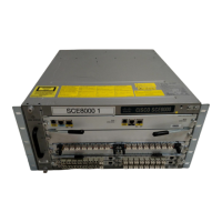
Chapter 2 Introduction to the Cisco SCE 8000 10 GBE Platform
Introduction to SIPs and SPAs
Introduction to SIPs and SPAs
SIPs and SPAs are a new carrier card and port adapter architecture used to increase modularity,
flexibility, and density for network connectivity. This section describes the SIPs and SPAs and provides
some guidelines for their use.
• SPA Interface Processors, page 2-6
• Specifying the SIP Subslot Location for a SPA, page 2-6
• Shared Port Adapters, page 2-7
• Modular Optics, page 2-8
• XFP Connections, page 2-9
SPA Interface Processors
The SIP module supported by the Cisco SCE 8000 chassis is the Cisco SCE 8000-SIP.
The following list describes some of the general characteristics of a SIP:
• SIP is a carrier card that inserts into a slot in the chassis like a line card. It provides no network
connectivity on its own.
• SIP contains one or more subslots (bays), which are used to house one or more SPAs. The SPA
provides interface ports for network connectivity.
• During normal operation the SIP should reside in the Cisco SCE 8000 chassis fully populated either
with functional SPAs in all subslots, or with a blank filler plate (SPA-BLANK=) inserted in all
empty subslots.
Specifying the SIP Subslot Location for a SPA
Cisco SCE 8000-SIP subslots begin their numbering with “0” and have a horizontal orientation.
Figure 2-3 shows the subslot numbering for the Cisco SCE 8000-SIP.
The Cisco SCE 8000-SIP supports four subslots for the installation of SPAs, as follows:
• SIP subslot 0—Top–left subslot
• SIP subslot 1—Top–right subslot
• SIP subslot 2—Bottom–left subslot
• SIP subslot 3—Bottom–right subslot
Figure 2-3 SPA Module Subslot Location
Sub-slot 0
Front of SCE8000-SIP
270900
Sub-slot 1
Sub-slot 2 Sub-slot 3
 Loading...