9-29
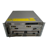
Cisco SCE8000 GBE Installation and Configuration Guide
Chapter 9 Removal and Replacement Procedures
Removing and Replacing Shared Port Adapters
Removing and Replacing Shared Port Adapters
This section provides information about the following tasks:
When removing and replacing the 1-port 10 GBE SPAs, follow these guidelines:
• SPAs must be installed in pairs. The Cisco SCE 8000 supports the following SPA configurations:
–
Two SPAs inserted in subslots 0 and 1
–
Four SPAs
• If only two SPAs are installed, sublots 2 and 3 must be covered by blank filler panels.
• Required Tools and Equipment, page 9-29
• Laser/LED Safety, page 9-29
• Handling SPAs, page 9-30
• SPA Installation and Removal, page 9-31
• Installing a SPA in a SIP, page 9-32
• Removing a SPA from a SIP, page 9-32
Required Tools and Equipment
You need the following tools and parts to install SPAs. If you need additional equipment, contact a
service representative for ordering information.
• Shared port adapter (SPA)
• Number 1 Phillips-head and a 3/16-inch flat-blade screwdriver
• Number 2 Phillips-head screwdriver
• Your own electrostatic discharge (ESD)-prevention equipment or the disposable grounding wrist
strap supplied with the SPA
• Antistatic container in which the SPA was shipped
Laser/LED Safety
An optical single-mode transmitter uses a small laser to transmit the light signal to the network ring.
Keep the transmit port covered whenever a cable is not connected to it. Although multi-mode
transceivers typically use LEDs for transmission, it is good practice to keep open ports covered and to
avoid staring into open ports or apertures. The transceivers aperture port contains a laser warning label,
as shown in Figure 9-15. These warnings apply to SPAs and XFP modules that transmit signals via an
optical carrier signal.
 Loading...