9-15
Cisco SCE8000 GBE Installation and Configuration Guide
Chapter 9 Removal and Replacement Procedures
Removing and Replacing Modules
Removing and Replacing Modules
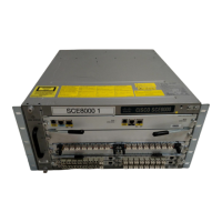
The Cisco SCE 8000 platform supports two types of modules:
• Service Control Module (Cisco SCE 8000-SCM-E)
• SPA Interface Processor (Cisco SCE 8000-SIP)
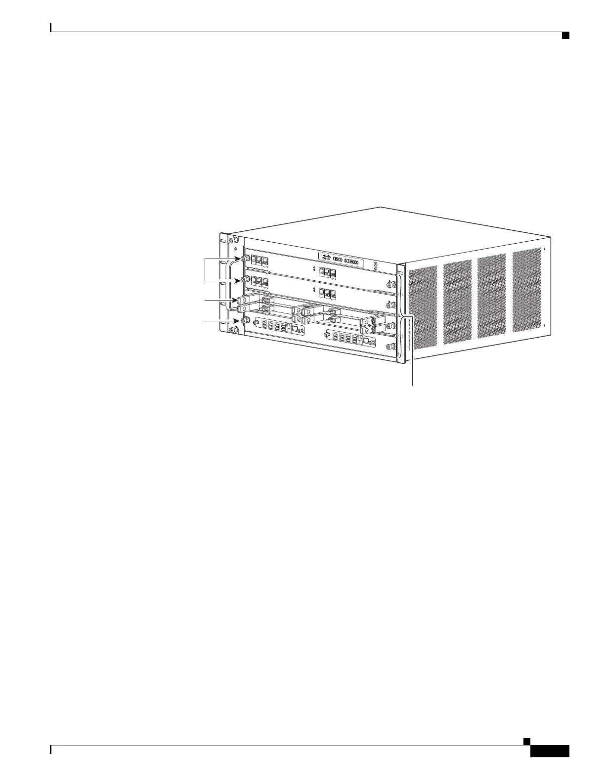
Figure 9-8 shows the position of these modules in the Cisco SCE 8000 chassis.
Figure 9-8 Slot Numbers on Cisco SCE 8000 Chassis
Required Tools
These tools are required to remove or install modules in the Cisco SCE 8000 chassis:
• 3/16-inch flat-blade screwdriver
• Number 2 Phillips-head screwdriver
• Wrist strap or other grounding device
• Antistatic container that the module was shipped in
Handling SIPs
Each SIP circuit board is mounted to a metal carrier and is sensitive to electrostatic discharge (ESD)
damage.
FA
N STA
TUS
S
C
M
1
S
C
M
2
S
I
P
3
4
SCE8
00
0-F
A
N
S
Y
ST
E
M
P
OW
E
R
O
PTICAL
B
YPASS
S
T
A
T
U
S
A
U
X
PO
R
T2
L
I
N
K
AC
TI
VE
MA
STER
S
C
E8000
EX
T
E
N
DE
D
S
E
R
V
I
CE
C
O
NT
R
O
L
M
O
D
U
LE
O
PTI
C
A
L
B
Y
P
A
S
S
O
PT
I
C
A
L
B
Y
P
A
S
S
C
ON
SO
LE
1
0
1
0
0
1
0
0
0
LI
N
K
AC
T
I
V
E
P
O
R
T
1
A
C
A
B
C
D
B
D
S
TAT
U
S
C
T
R
L
O
P
B
-
S
C
E
8
K
-
M
M
O
P
T
I
CA
L
B
Y
P
A
S
S
1
T
X
R
X
T
X
R
X
T
X
R
X
T
X
R
X
A
C
A
B
C
D
B
D
S
TA
T
U
S
C
T
R
L
O
PB
-
S
CE8
K
-
M
M
OPT
IC
AL
B
YPASS2
T
X
R
X
T
X
R
X
T
X
R
X
T
X
R
X
S
Y
S
TEM
P
OWE
R
O
PTICAL
B
YPASS
ST
A
T
U
S
AUX
P
ORT
2
10
100
1000
L
I
N
K
A
C
T
I
VE
M
A
STER
S
C
E8000 EX
T
E
N
DE
D
S
E
R
V
I
C
E
C
O
NT
RO
L
M
O
DULE
S
C
E
8
0
0
0
-S
CM-E
S
C
E
8
0
0
0-S
CM-E
S
CE
8
0
0
0
-
S
IP
C
ON
SO
L
E
1
0
1
0
0
1
0
0
0
LI
N
K
AC
T
I
V
E
PO
R
T
1
O
P
T
I
C
A
L
B
Y
P
A
S
S
OPT
I
C
AL
B
Y
P
ASS
S
T
ATUS
A
C
T
I
V
E
/
L
I
N
K
S
P
A
-
1
X
1
0
GE-
L-
V
2
S
T
A
TU
S
A
C
T
I
V
E
/
L
I
N
K
S
P
A
-
1
X
1
0
G
E-
L-
V
2
S
T
A
T
U
S
A
C
T
I
V
E
/
L
I
N
K
S
P
A
-1
X
10
G
E
-
L
-
V2
S
T
A
T
U
S
A
C
T
I
V
E
/
L
I
N
K
S
P
A
-1
X
10
GE
-
L
-
V2
10
1
00
1000
270889
Slots 1-4
(top to bottom)
SCE8000-
SCMs
SCE8000-
SIP
Optional
Optical Bypass
Modules
 Loading...