9-14
Cisco SCE8000 GBE Installation and Configuration Guide
Chapter 9 Removal and Replacement Procedures
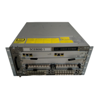
Installing the Fan Assembly
Installing the Fan Assembly
Step 1 Hold the fan assembly with the fans facing to the right and the FAN STATUS LED at the bottom. (See
Figure 9-7.)
Step 2 Place the fan assembly into the front chassis cavity so that it rests on the chassis, and then lift the fan
assembly up slightly, aligning the top and bottom chassis guides.
Step 3 Push the fan assembly into the chassis until the power connector seats in the backplane and the captive
installation screws make contact with the chassis.
Step 4 Tighten the captive installation screws.
Step 5 Verify that fans are operational:
• Listen for the fans; you should immediately hear them operating. If you do not hear them, ensure
that the fan assembly is inserted completely in the chassis and the faceplate is flush with the switch
back panel.
• Verify that the FAN STATUS LED is green. If the LED is red, one or more fans is faulty.
 Loading...