3-4
Cisco SCE8000 GBE Installation and Configuration Guide
Chapter 3 Cisco SCE 8000 Topology and Topology-Related Parameters
Physical Topologies
Physical Topologies
The following sections are descriptions of several physical topologies that Cisco SCE 8000 supports:
• Cisco SCE 8000 Interface Numbering, page 3-4
• Single Cisco SCE 8000 Topologies, page 3-4
• Dual Cisco SCE 8000 Topology (Cascade), page 3-8
• Multi-Gigabit Service Control Platform (MGSCP) Topology, page 3-9
Cisco SCE 8000 Interface Numbering
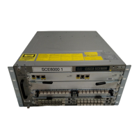
Figure 3-1 shows the numbering of the Cisco SCE 8000 interfaces as indicated in the topology diagrams
in this chapter. The interface numbering is explained as follows:
• First digit is the slot number (always 3).
• Second digit is the number of the sub-slot or SPA module (0 to 3).
• Third digit is the number of the interface on the designated SPA module (always 0).
• Interfaces 3/0/0 and 3/2/0 are on the two left SPA modules and are the Subscriber-side interfaces.
• Interfaces 3/1/0 and 3/3/0 are on the two right SPA modules and are the Network-side interfaces.
Figure 3-1 Cisco SCE 8000 Interface Numbering
Single Cisco SCE 8000 Topologies
A single Cisco SCE 8000 supports both single 10 GBE link and dual 10 GBE link topologies:
• Single Link: Inline Topology, page 3-5
• Dual Link: Inline Installation, page 3-5
• Single Link: Receive-only Topology, page 3-6
• Dual Link: Receive-Only Topology, page 3-7
270591
Subscriber Network
Subscriber Network
3/0/0
3/2/0
3/1/0
3/3/0
 Loading...