161
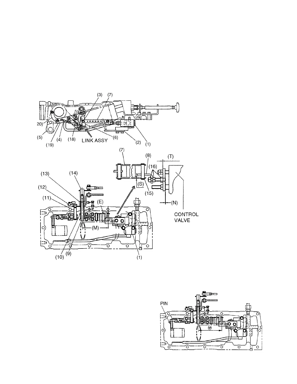
(2) HYDRAULIC CONTROL LINKAGE
REASSEMBLING
*Reassemble the hydraulic control linkage with
reverse procedure of disassembling. Use
following values as adjustment and service
standard for reassembling.
1. Control valve installation
1) After install the control valve, adjust the
dimension (M) to 132.2~132.8 mm with
pushing the spool to make [0.0118~0.0354
in] of clearance at (T) by adjusting position
of plate (8).
2) Sticking out amount (N) of screw on plate
(8) should not exceed [0.039in.] from valve
plate.
(1)CONTROL VALVE
(2)GUIDE
(3)ROLLER
(4)SPRING
(5)POWER ARM
(6)LINK
(7)LINK H
(8)PLATE
(9)POSITION SHAFT
(10)DRAFT SHAFT
(11)SHAFT
(12)ARM
(13)LEVER B
(14)LEVER A
(15)LINER
(16)NUT
(17)LINK B
(18)LINK J
(19)LINK
(20)LINK E
 Loading...