Home
Cub Cadet
Tractor
7360SS
Cub Cadet 7360SS User Manual
4
of 1
of 1 rating
170 pages
Give review
Manual
Specs
To Next Page
To Next Page
To Previous Page
To Previous Page
Loading...
43
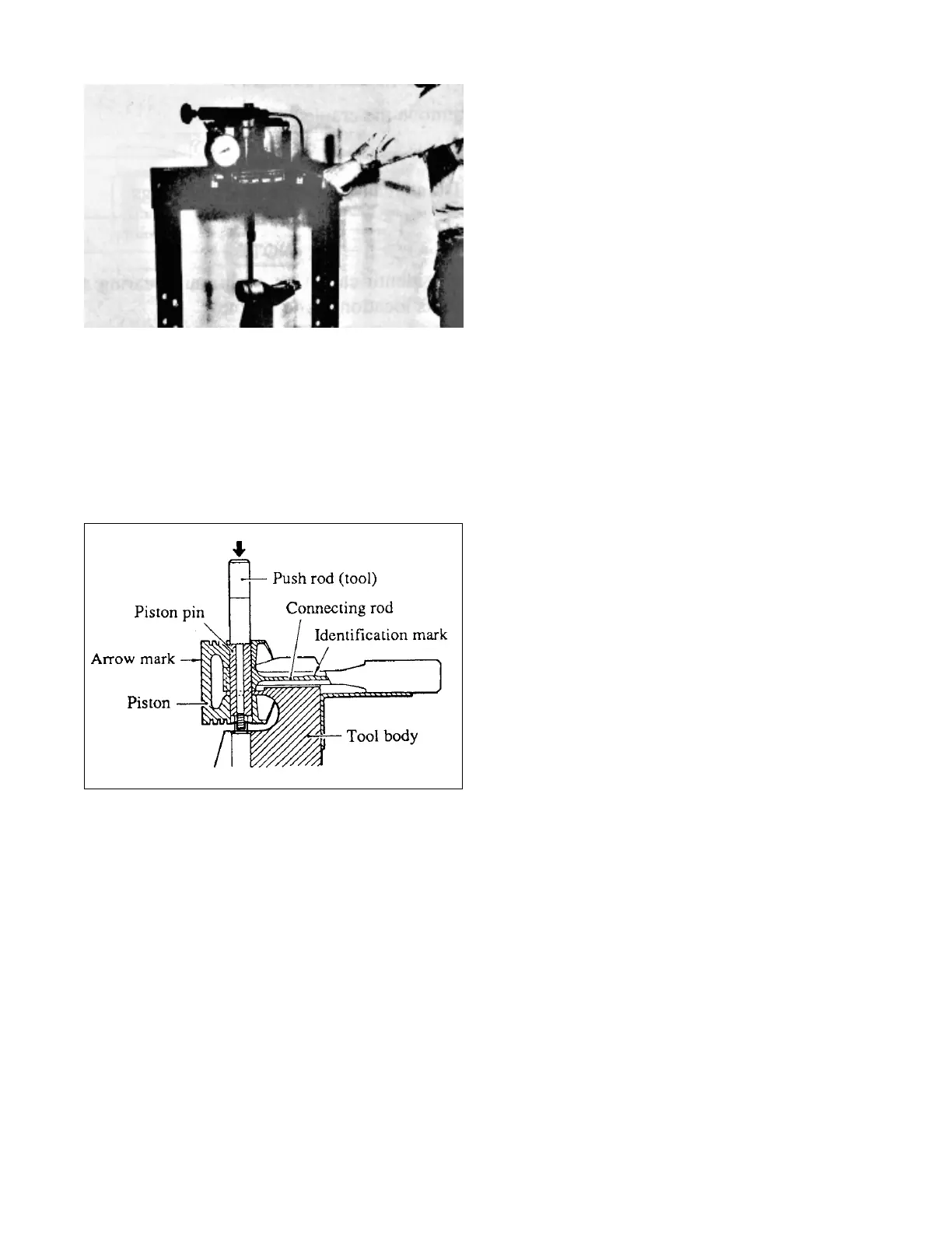
(2)Insert the push rod of the tool into the
bore in the piston for the piston pin and,
using an arbor press, remove the piston pin.
(3)Use this Piston Pin Setting
T
ool to install
the connecting rod to the piston.
43
45
Table of Contents
Table of Contents
2
Index
2
General
4
Safety
5
Location of Engine Model, Engine Serial no and Tractor Serial No. Identifications
7
Capacities
8
Fuel Specifications
8
Fuel Injectors
8
Specification and Data
8
Power Transmission Diagram
9
Standard Bolt Torques
10
Tightening Torques
10
Precautions for Disassembly
11
Inspection
12
Gears
12
Cleaning
12
General Information
12
Assy Removal and Reinstallation
13
4Wd Shaft Removal
14
Steering Hose Removal
14
Battery Code Disconnection
14
Front Axle Assy Removal and Reinstallation
14
Front Axle Assy Reinstallation
15
Front & Rear Holder Removal
15
Harnesses Removal
16
Engine Assy Removal and Reinstallation
16
Panel Removal
17
Engine Removal
19
Engine Reinstallation
20
Center Case Removal
22
Clutch Housing, Transmission Case, Rear Axle Case and Hydraulic Lift Case Removal and Reinstallation
22
Hydraulic Lift Case Removal
23
Rear Axle Case Removal
23
Housing Reinstallation
24
Hydraulic Lift Case Reinstallation
24
Rear Axle Case Reinstallation
24
Center Case Reinstallation
25
Clutch Housing Reinstallation
25
Compression Pressure Measurement
26
Determining When to Overhaul the Engine
26
Engine
26
Basic Precaution for Disassembly and Assembly
27
Coolant Draining
28
Engine Oil Draining
28
Fuel Knock
29
Trouble Shooting
29
Overheating
30
Black Exhaust Smoke
31
Erratic Idle Speeds
31
Low Power or Loss of Power
32
Starting System Troubleshooting
33
Cylinder Head Disassembly
35
Disassembling
35
Rocker Shaft Assembly Removal
35
Rocker Shaft Disassembly
35
Cylinder Head Assembly Removal
36
Valve and Valve Spring Removal
36
Valve Stem Seal Removal
36
Flywheel Removal
37
Timing Gear/Flywheel
37
Crankshaft Pulley Removal
38
Oil Seal Case Removal
38
Rear Plate Removal
38
Speedometer Driven Gear Removal
38
Camshaft Removal
39
Idler Gear Removal
39
Timing Gear Backlash Measurement
39
Timing Gear Case Removal
39
Front Plate Removal
40
Fuel Injection Pump Camshaft Removal
40
Gear Removal
40
Oil Pan Removal
41
Connecting Rod Cap Removal
42
Oil Screen Removal
42
Piston Removal
42
Crankshaft Removal
43
Main Bearing Cap Removal
43
Piston Separation from Connecting Rod
43
Cylinder Head Bottom Face Cleaning
45
Cylinder Head Reassembling
45
Reassembling
45
Valve Stem Seal Installation
45
Cylinder Head Gasket Installation
46
Cylinder Head Installation
46
Valve Block Installation
46
Valve Spring Installation
46
Cylinder Head Bolt Tightening
47
Rocker Shaft Assembling
47
Valve Push Rod Installation
47
Flywheel Reassembling
48
Front Plate Installation
48
Oil Pump Installation
48
Timing Gear
48
Camshaft Installation
49
Engine Turning
49
Fuel Injection Pump Camshaft Installation
49
Idler Gear Installation
50
P.T.O. Gear Installation
50
Speedometer Driven Gear Installation
50
Timing Gear Case Installation
50
Flywheel Installation
51
Oil Seal Case Installation
51
Rear Plate Installation
51
Tappet Installation
51
Rocker Cover Installation
52
Rocker Shaft Assembly Installation
52
Valve Clearance Adjustment
52
Cylinder Block, Crankshaft,Pistons and Oil Pan Reassembling
53
Main Bearing Installation
53
Crankshaft Installation
54
Main Bearing Cap Installation
54
Piston Assembling to Connecting Rod
55
Side Seal Installation
55
Piston and Connecting Rod Installation
56
Piston Ring Installation
56
Connecting Rod Cap Installation
57
Oil Screen Installation
57
Oil Pan Installation
58
Cooling Fan Removal
59
Cooling System Disassembly Removal
59
Thermostat Case Removal
59
Water Pump Assembly Removal
59
Fuel Injection Nozzle Removal
60
Fuel Injection Pipe Removal
60
Fuel System Disassembly Removal
60
Governor Assembly Removal
60
Air Inlet Cover Removal
61
Exhaust Manifold Removal
61
Lublication System Removal
62
Oil Filter Removal
62
Oil Pressure Switch Removal
62
Pressure Relief Valve Removal
62
Brush Holder Removal
63
Electrical System Disassembly
63
Magnetic Switch
63
Starter Disassembly
63
Bearing Removal
64
Center Bracket Removal
64
Cover Removal
64
Pinion Shaft Removal
64
Alternator
65
Disassembly Procedure
65
Injection Pump
66
Electrical System
67
Pinion Shaft End Play Adjustment
67
Stopper Ring Installation
67
Pinion Clearance Adjustment
68
Shutoff Solenoid Installation
70
Cooling System Reinstallation
71
Thermostat Installation
71
Thermoswitch and Thermounit
71
Water Pump Installation
71
Alternator Installation
72
Glow Plug Installation
72
Oil Filter Installation
73
Oil Pressure Switch Installation
73
Pressure Relief Valve Installation
73
Fuel Injection Nozzle Installation
74
Fuel System Reinstallation
74
Governor Assembly Installation
74
Sliding Sleeve Installation
74
Fuel Injection Line Installation
75
Clearance between Pinion and Housing
76
No-Load Characteristics
76
Testing before Disassembly Removal
76
Inspection before Removal
78
Precautions for Removal
78
Testing Voltage Setting
78
Connections for Testing Voltage Setting
79
Testing Output Characteristics
79
Cylinder Head
80
Inspection
80
Rocker Arms and Rocker Shaft
80
Valve Springs
80
Diameter of Valve Stem
81
Valve Guide Replacement
81
Valve Push Rods
81
Valves, Valve Guides and Valve Seats
81
Valve Refacing
82
Valves
82
Valve Lapping
83
Valve Seat Refacing
83
Bushing Replacement
85
Camshaft
85
Clearance between Journal and Bushing
85
Timing Gears and Flywheel
85
Cam Contact Face
86
Fuel Injection Pump Camshaft
86
Idler Gear
86
Tappets
86
Flywheel and Ring Gear
87
Idler Shaft Replacement
87
Clearance between Ends of Piston Ring
88
Diameter of Piston
88
Pistons, Piston Rings and Piston Pins
88
Clearance between Piston Pin and Piston
89
Connecting Rods
89
Bore
92
Crankshaft Gear Installation
92
Cylinder Block
92
Runout
92
Checking Cylinder Block Top Face for Warpage
93
Warpage of Top Face
93
Cooling System
94
Thermostat
94
Water Pump
94
Lubrication System
95
Oil Pressure Switch
95
Pressure Relief Valve
95
Brush Holders
96
Brush Spring Tension
96
Commutator Runout
96
Starter
96
Diameter of Commutator
97
Mica Undercut
97
Testing for Grounded Circuit
97
Testing for Open Circuit
97
Bearings
98
Field Coils
98
Front Bracket
98
Overrunning Clutch
98
Diodes
99
Field Coil
99
Stator Core
99
Brushes
100
Glow Plug
100
Adjustment
101
Valve Clearance
101
Fuel Injection Timing
102
Disassembly Sequence and Inspection Points
104
Idler R.p.M Setting
104
Injection Nozzle
105
Injection Pressure
105
Orifice Restriction Test
105
Nozzle Tip Washing and Replacement
106
Fan Belt
107
Special Tools
108
Clutch
109
Disassembling Clutch Assy
109
Reassembling Clutch Lever
109
Reassembling Clutch Assy
110
Clutch Pedal Adjustment
110
Stopper Adjustment
111
Clutch Disk Boss and Main Shaft
111
Clutch Disk
111
Clutch Housing Disassembling
112
Cover B Sub Assy Removal
112
Cover B Sub Assy Disassembling
112
Transmission
112
4Wd Shaft Disassembling
113
Disassemble PTO Hydraulic Clutch Assy
113
Center Case Disassembling
114
Cover C Sub Assy Disassembling
114
Cover C Sub Assy Removal
114
Cover D Removal
115
Cover D Sub Assy Disassembling
115
Disassemble Shuttle Shift Control
115
Rear Differential Case Removal
116
Transmission Case Disassembly
116
Cover E Sub Assy Disassembling
117
Cover E Sub Assy Removal
117
Clutch Housing Reassembling
118
Cover B Reassembling
118
Cover B Reinstallation
118
PTO Shaft Removal
118
4Wd Shaft Reassembling
119
Center Case Reassembling
119
Cover C Sub Assy Reinstallation
119
PTO Hydraulic Clutch Reassembling
119
Cover C Reassembling
120
Drive Shaft
120
Select Shaft
120
Cover D Reinstallation
121
Cover D Sub Assy Reassembling
121
Cover E Sub Assy Reassembling
122
Differential Lock Pedal
122
Rear Differential Case Reassembling
122
Transmission Case Reassembling
122
4WD Shaft
123
Pinion Shaft
123
PTO Drive Shaft
123
Pto Shaft Reinstallation
123
Check and Maintenance
124
Check the Synchromesh Gear
124
Checking the Gear Contact Pattern
124
Differential Gear and Pinion Shaft
124
Check of Double Cone Synchromesh
125
Synchronizer Sleeve ,Hub
125
Synchronizer Spring
125
Checking the Hydraulic Clutch
126
Piston and Seal Ring
126
Steel Plate
126
Rear Axle Disassembling
127
Rear Axle Assy Removal
127
Rear Axle Assy Disassembling
127
Rear Axle
127
Brake Assy Removal
128
Brake Control Disassembling
128
Differential Case Assy Reassembling
129
Brake Assy Reassembling
130
Rear Axle Reassembling
130
Brake Control Reassembling
131
Brake L.h. Reassembling
131
Brake R.h. Reassembling
131
Check and Maintenance
132
Holder Assy Disassembling
133
Front Axle Removal
133
Front Axle
133
King Pin Case Disassembling
134
Knuckle Arm, Final Case Disassembling
134
Center Case, Diff. Case Disassembling
135
Front Axle Assembly
136
Front Axle Reassembling
136
Knucle Arm and Final Case
137
King Pin Case Reassembling
138
Center Case and Diff. Case
139
Clearance at Bushing
140
Diff. Case Installation
140
Front Axle Check and Maintenance
140
Clearance between Holder and Knuckle Arm
141
Clearance between Knuckle Arm Holder and Bushing
141
Operator Control Area Removal
142
Steering Wheel Removal
142
Steering
142
Steering Unit Disassembling
143
Steering Unit Removal
143
Steering Wheel Disassembling
143
Controls Disassembling
144
Rotary Disassembling
144
Hydraulic Cylinder Assy Removal
145
Hydraulic Cylinder Disassembling
145
Hydraulic Cylinder Assy Disassembling
146
Adjustment of Tilt Lever
147
Operator Control Area Reassembling
147
Steering Wheel Reinstallation
147
Steering Unit Reassembling
148
Steering Wheel Reassembling
148
Rotary Reassembling
149
Check and Maintenance
153
Steering Wheel Free Play
153
Toe-In Adjustment
153
Main Hydraulics Disassembling
154
Hydraulic Pump Disassembling
154
Hydraulic Pump Removal
154
Hydraulics
154
Control Valve Disassembling
155
Control Valve Removal
155
Pump II Disassembling
155
Cylinder Disassembling
156
Hydraulic Lift Disassembling
156
Lift Shaft Disassembling
156
Hydraulic Linkage Disassembling
157
Hydraulic Linkage Removal
157
Flow Control Valve Disassembling
158
Position Control Lever Removal
158
Control Valve Assembling
159
Hydraulic Pumps Reassembling
159
Main Hydraulics Reassembling
159
Hydraulic Lift Reassembling
160
Lift Shaft and Cylinder Reassembling
160
Lift Shaft Reassembling
160
Valve Neutral Adjustment
160
Control Valve Installation
162
Hydraulic Control Linkage
162
Control Linkage Installation
163
O-Ring Installation to Shafts
163
Flow Control Valve Reassembling
164
Position Control Lever Reassembling
164
During the Installation
165
Filter Installation
165
Hydraulic Line Checking
165
Tightening Torques of Hydraulic Line
166
Clearance between Cylinder and Piston
167
Clearance of Bushing
167
Hydraulic Check and Maintenance
167
Hydraulic Lift System Checking
167
Electric Diagram
169
Electrics
169
Specications
170
Electrical
170
4
Based on 1 rating
Ask a question
Give review
Questions and Answers:
Need help?
Do you have a question about the Cub Cadet 7360SS and is the answer not in the manual?
Ask a question
Cub Cadet 7360SS Specifications
General
Brand
Cub Cadet
Model
7360SS
Category
Tractor
Language
English
Related product manuals
Cub Cadet 73
48 pages
Cub Cadet 7304
52 pages
Cub Cadet 7300
138 pages
Cub Cadet 7305
138 pages
Cub Cadet 7254
52 pages
Cub Cadet 7264
52 pages
Cub Cadet 7260
321 pages
Cub Cadet 7530
126 pages
Cub Cadet 7265
321 pages
Cub Cadet 7000 Series
52 pages
Cub Cadet PRO Z 760 S KW
32 pages
Cub Cadet Domestic Series 7000
88 pages