N O T I C E
The motor cable must be shielded/armored. If an unshielded/unarmored cable is used, some EMC requirements are not complied
with. Use a shielded/armored motor cable to comply with EMC emission specications.
For more information on EMC, see 10.16 EMC-compliant Installation.
Shielding of cables
Avoid installation with twisted shield ends (pigtails). They spoil the shielding eect at higher frequencies. If it is necessary to break
the shield to install a motor isolator or contactor, continue the shield at the lowest possible HF impedance. Connect the motor cable
shield to both the decoupling plate of the drive and the metal housing of the motor. Make the shield connections with the largest
possible surface area (cable clamp) by using the installation devices within the drive.
Cable length and cross-section
The drive has been EMC-tested with a given length of cable. Keep the motor cable as short as possible to reduce noise level and
leakage currents.
Switching frequency
When drives are used together with sine-wave lters to reduce the acoustic noise from a motor, the switching frequency must be set
according to the instructions in parameter 14-01 Switching Frequency.
N O T I C E
In motors without phase insulation, paper, or other insulation reinforcement suitable for operation with voltage supply, use a
sine-wave lter on the output of the drive.
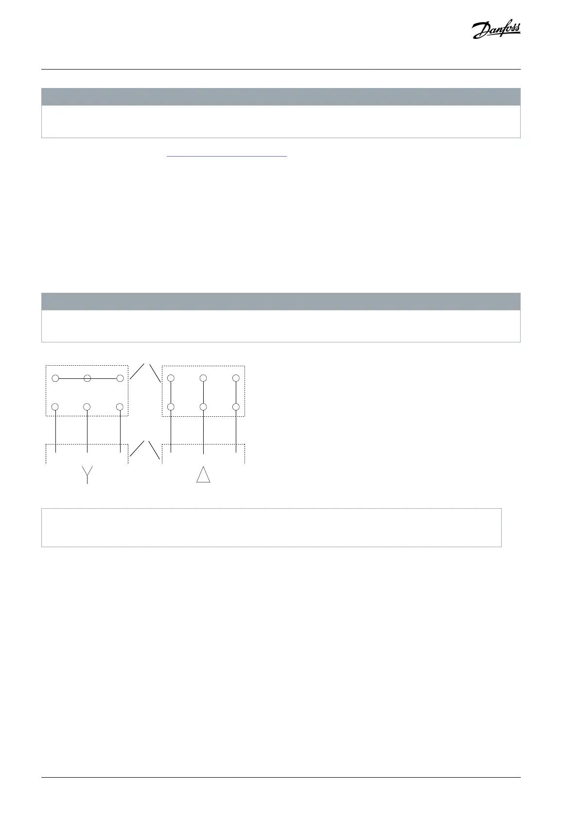
Illustration 62: Motor Cable Connection
10.3.2 IT Grid Connection
Mains supply isolated from ground
If the drive is supplied from an isolated mains source (IT mains, oating delta, or grounded delta) or TT/TN-S mains with grounded
leg, the RFI switch is recommended to be turned o via parameter 14-50 RFI Filter on the drive and parameter 14-50 RFI Filter on the
lter. For more detail, see IEC 364-3. In the o position, the lter capacitors between the chassis and the DC link are cut o to avoid
damage to the DC link and to reduce the ground capacity currents, according to IEC 61800-3. If optimum EMC performance is nee-
ded, or parallel motors are connected, or the motor cable length is above 25 m (82 ft), Danfoss recommends setting parameter 14-50
RFI Filter to [1] On. Refer also to the Application Note, VLT on IT grid. It is important to use isolation monitors that are rated for use
together with power electronics (IEC 61557-8).
Danfoss does not recommend using an output contactor for 525–690 V drives connected to an IT mains network.
AJ300847815559en-000101 / 130R0337110 | Danfoss A/S © 2020.09
Electrical Installation
Considerations
VLT® AQUA Drive FC 202
Design Guide
 Loading...


