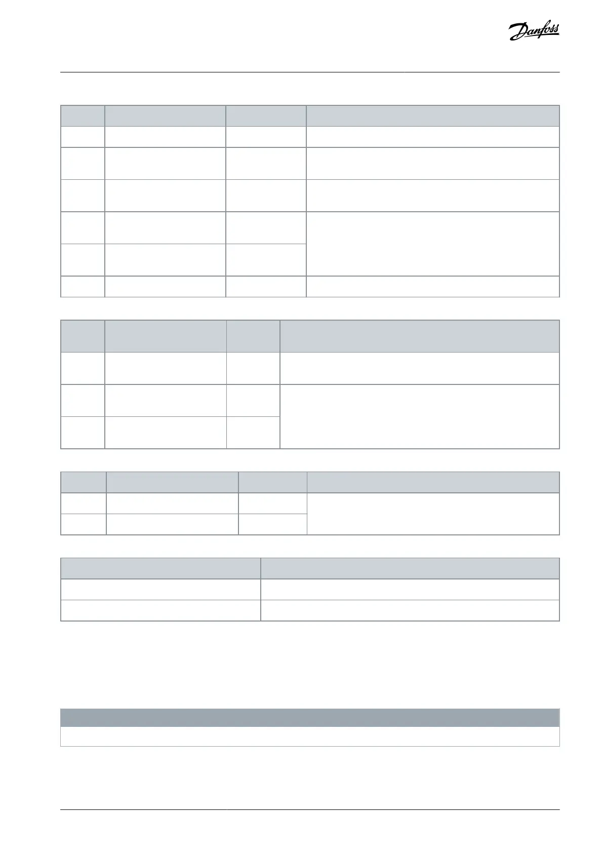
Table 64: Analog Inputs/Outputs
Common for analog output.
Parameter 6-50 Terminal 42
Output
Programmable analog output. 0–20 mA or 4–20 mA at a maxi-
mum of 500 Ω.
10 V DC analog supply voltage potentiometer or thermistor.
15 mA maximum.
Parameter group 6-1* Analog
Input 1
Analog input. For voltage or current. Switches A53 and A54 se-
lect mA or V.
Parameter group 6-1* Analog
Input 2
Table 65: Serial Communication
Integrated RC-lter for cable shield. ONLY for connecting the shield if
EMC problems occur.
Parameter group 8-3* FC Port
Settings
RS485 interface. A control card switch is provided for termination re-
sistance.
Parameter group 8-3* FC Port
Settings
Table 66: Relays
Parameter 5-40 Function Relay [0]
Form C relay output. For AC or DC voltage and resistive or in-
ductive loads.
Parameter 5-40 Function Relay [1]
Table 67: Additional Terminals
The location of the outputs depend on the drive conguration.
Terminals on built-in optional equipment
See the manual provided with the equipment option.
10.6 Fuses and Circuit Breakers
10.6.1 Fuse Recommendations
Fuses ensure that possible damage to the drive is limited to damages inside the unit. Danfoss recommends fuses and/or circuit
breakers on the supply side as protection. For further information, see Application Note Fuses and Circuit Breakers.
N O T I C E
Use of fuses on the supply side is mandatory for IEC 60364 (CE) and NEC 2009 (UL) compliant installations.
AJ300847815559en-000101 / 130R0337 | 125Danfoss A/S © 2020.09
Electrical Installation
Considerations
VLT® AQUA Drive FC 202
Design Guide
 Loading...


