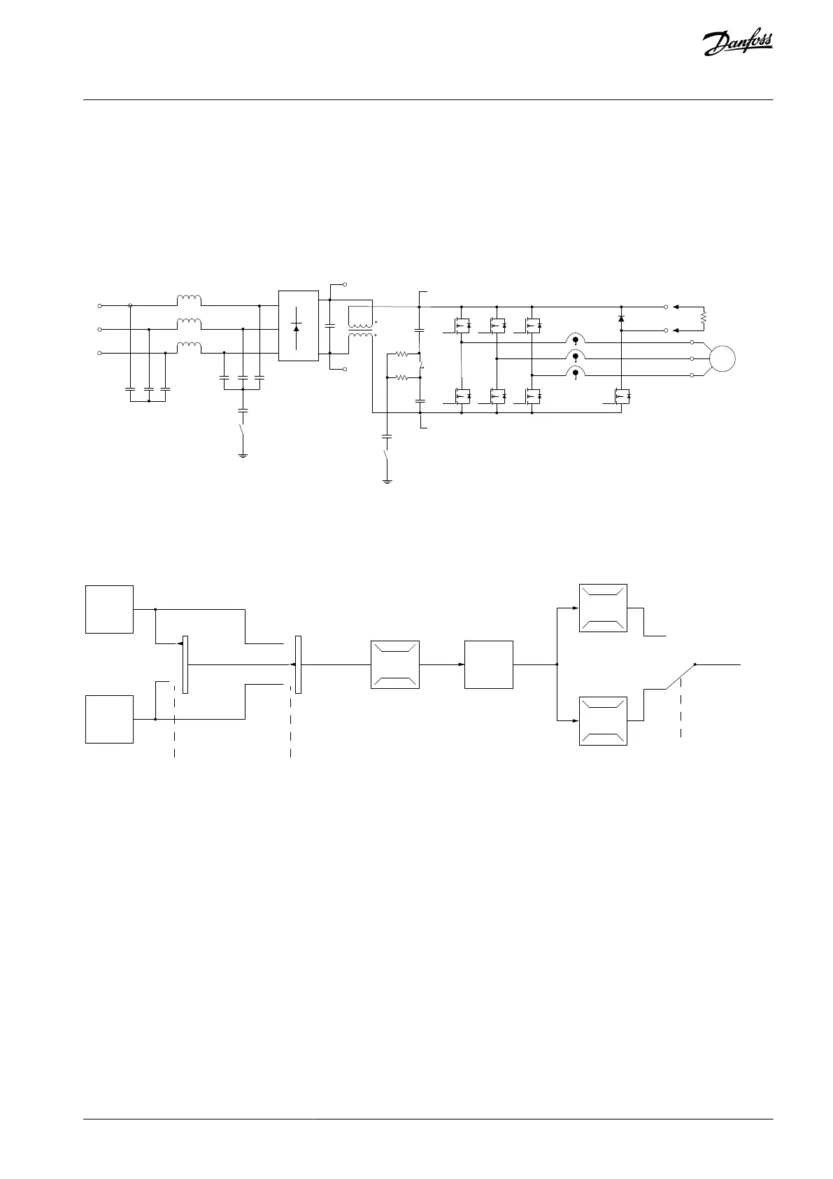
11.4 Control Principle
The drive recties AC voltage from mains into DC voltage, after which the DC voltage is converted into an AC current with a variable
amplitude and frequency.
The drive supplies the motor with variable voltage/current and frequency, standard induction motors, and non-salient PM motors.
The drive manages various motor control principles such as U/f special motor mode and VVC
+
. Short-circuit behavior of the drive
depends on the 3 current transducers in the motor phases.
The VLT® drives can run in open-loop and closed-loop application. Select the conguration mode when programming the drive.
Inrush
R inr
Load sharing -
Load sharing +
LC Filter -
(5A)
Illustration 90: Control Structure Diagram
11.4.1 Control Structure Open Loop
100%
P 3-13
Reference
site
Local
reference
scaled to
RPM or Hz
Auto mode
Hand mode
LCP Hand on,
off and auto
on keys
Linked to hand/auto
Local
Reference
Ramp
P 4-10
Motor speed
direction
To motor
control
Reference
handling
Remote
reference
P 4-13
Motor speed
high limit [RPM]
P 4-14
Motor speed
high limit [Hz]
P 4-11
Motor speed
low limit [RPM]
P 4-12
Motor speed
low limit [Hz]
P 3-4* Ramp 1
P 3-5* Ramp 2
Illustration 91: Open-loop Structure
In open-loop congurations, the resulting reference from the reference handling system or the local reference is received and fed
through the ramp limitation and speed limitation before being sent to the motor control.
The output from the motor control is then limited by the maximum frequency limit.
11.4.2 Control Structure Closed Loop
The internal controller allows the drive to become a part of the controlled system. The drive receives a feedback signal from a sensor
in the system. It then compares this feedback to a setpoint reference value and determines the error, if any, between these 2 signals.
It then adjusts the speed of the motor to correct this error.
For example, consider a pump application where the speed of a pump is to be controlled to ensure a constant static pressure in a
pipe. The static pressure value is supplied to the drive as the setpoint reference. A static pressure sensor measures the actual static
pressure in the pipe and supplies this data to the drive as a feedback signal. If the feedback signal is greater than the setpoint refer-
ence, the drive slows the pump down to reduce the pressure. In a similar way, if the pipe pressure is lower than the setpoint refer-
ence, the drive automatically speeds the pump up to increase the pressure provided by the pump.
AJ300847815559en-000101 / 130R0337 | 163Danfoss A/S © 2020.09
Basic Operating Principles
VLT® AQUA Drive FC 202
Design Guide
 Loading...


