Table 97: Harmonic Currents versus RMS Input Current
The voltage distortion on the mains supply voltage depends on the size of the harmonic currents multiplied by the mains impe-
dance for the frequency in question. The total voltage distortion (THDi) is calculated based on the individual voltage harmonics
using this formula:
THDi =
I
5
2
+ I
7
2
+ ..... I
n
2
I
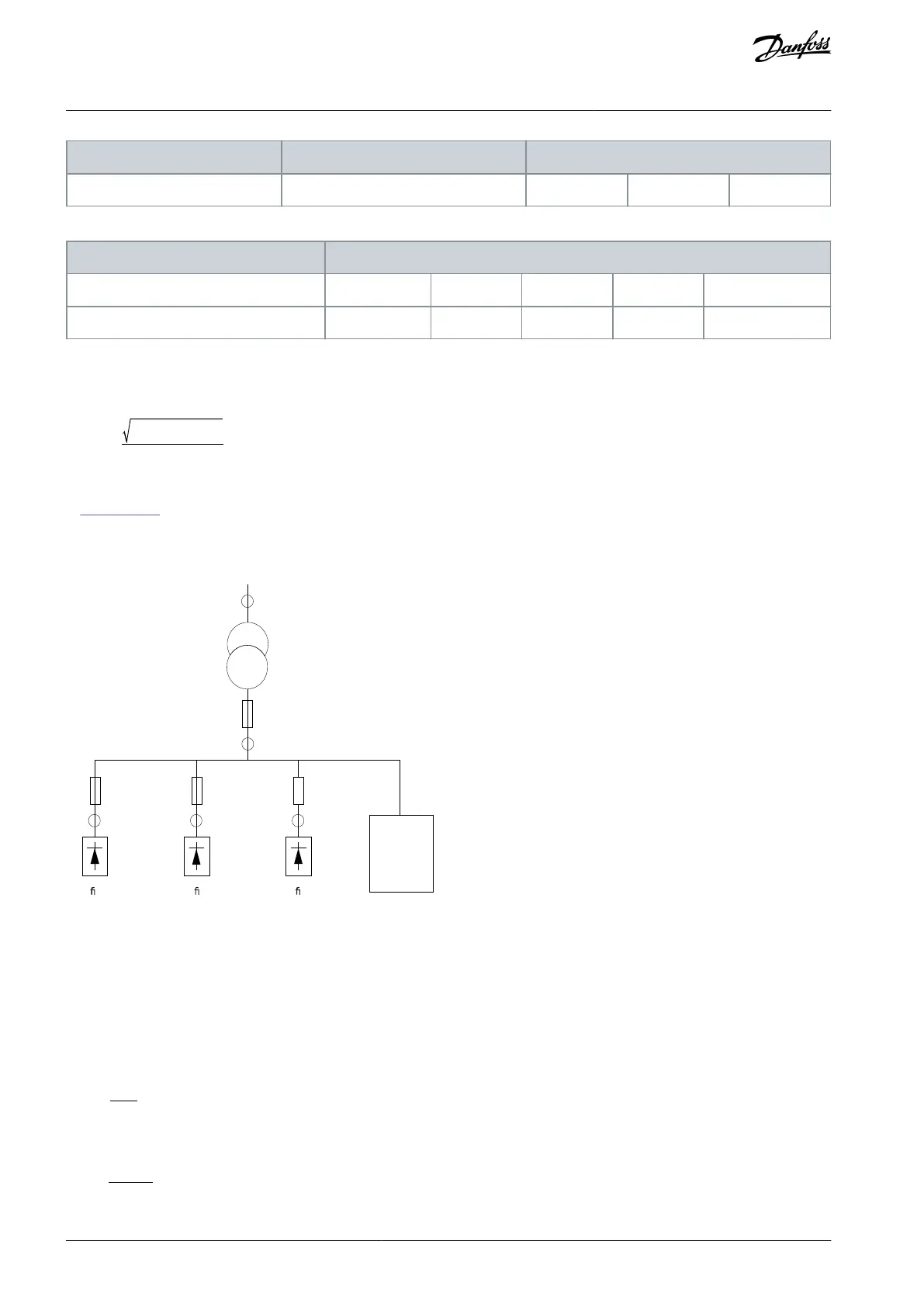
10.17.2 Eect of Harmonics in a Power Distribution System
In Illustration 82, a transformer is connected on the primary side to a point of common coupling PCC1 on the medium voltage sup-
ply. The transformer has an impedance Z
xfr
and feeds several loads. The point of common coupling where all loads are connected
together is PCC2. Each load is connected through cables that have an impedance Z
1
, Z
2
, Z
3
.
P C C2
P C C3 P C C3 P C C3
Z
Z Z Z
R e c t i e r 1 R e c t i e r 2 R e c t i e r 3
O t h e r
L o a d s
x f r
2 1 3
Illustration 82: Small Distribution System
Harmonic currents drawn by non-linear loads cause distortion of the voltage because of the voltage drop on the impedances of the
distribution system. Higher impedances result in higher levels of voltage distortion.
Current distortion relates to apparatus performance and it relates to the individual load. Voltage distortion relates to system per-
formance. It is not possible to determine the voltage distortion in the PCC knowing only the load’s harmonic performance. To pre-
dict the distortion in the PCC, the conguration of the distribution system and relevant impedances must be known.
A commonly used term for describing the impedance of a grid is the short circuit ratio R
sce
. R
sce
is dened as the ratio between the
short circuit apparent power of the supply at the PCC (S
sc
) and the rated apparent power of the load (S
equ
).
R
sce
=
S
ce
S
equ
where
S
sc
=
U
2
Z
supply
andS
equ
= U ∗ I
equ
AJ300847815559en-000101 / 130R0337154 | Danfoss A/S © 2020.09
Electrical Installation
Considerations
VLT® AQUA Drive FC 202
Design Guide
 Loading...


