•
•
•
•
•
•
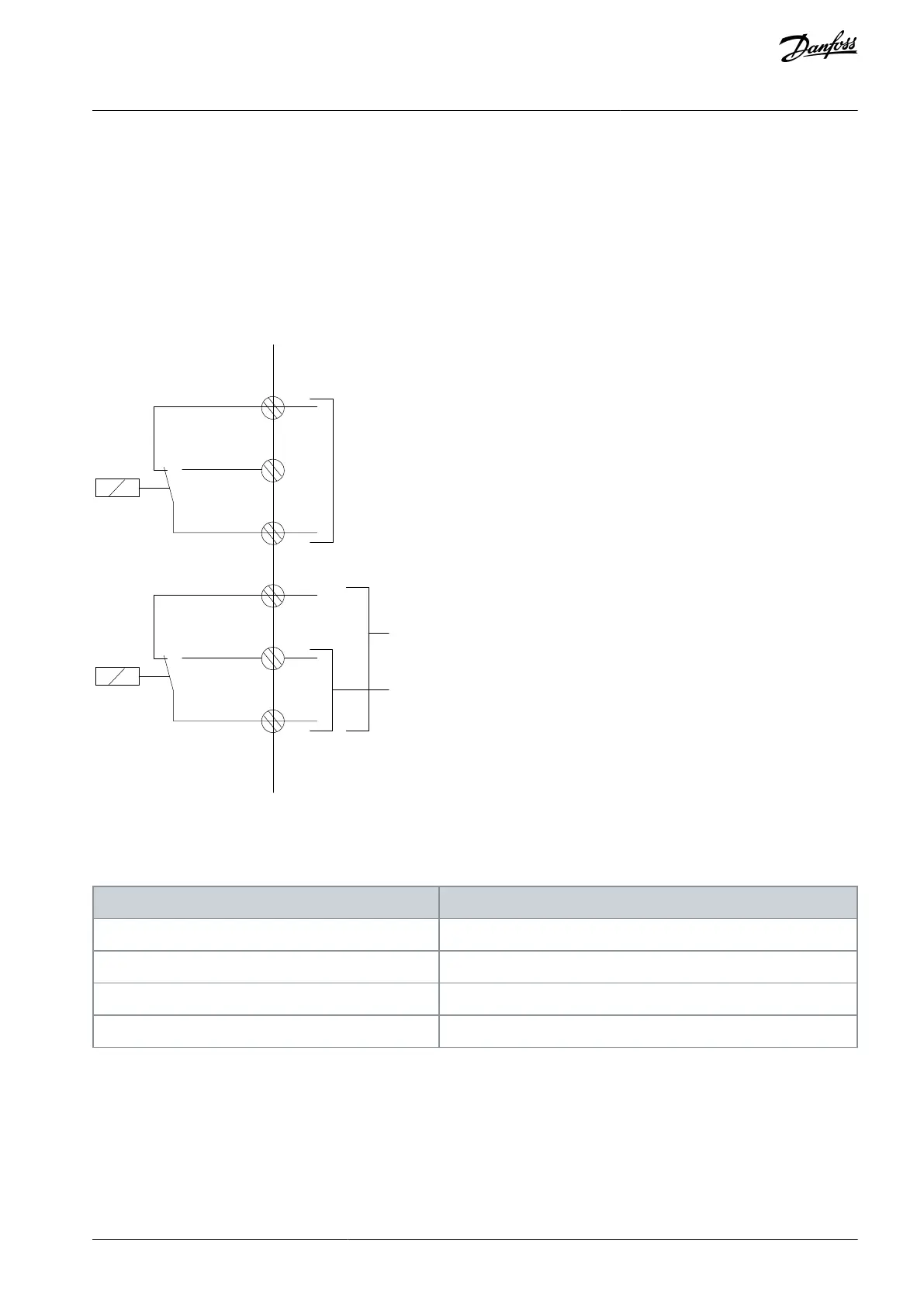
Terminal 01: Common.
Terminal 02: Normally open 240 V.
Terminal 03: Normally closed 240 V.
Relay 2
Terminal 04: Common.
Terminal 05: Normally open 400 V.
Terminal 06: Normally closed 240 V.
More relay outputs are available by using the VLT® Relay Option Module MCB 105.
Relay1
Relay2
03
02
240 V AC, 2 A
240 V AC, 2 A
400 V AC, 2 A
01
06
05
04
e30ba047.11
Illustration 71: Relay Outputs 1 and 2
To set the relay output, see parameter group 5-4* Relays.
Table 84: Description of Relays
10.8 Motor
All types of 3-phase asynchronous standard motors can be used with a drive. The factory setting is for clockwise rotation with the
drive output connected as follows:
AJ300847815559en-000101 / 130R0337 | 135Danfoss A/S © 2020.09
Electrical Installation
Considerations
VLT® AQUA Drive FC 202
Design Guide
 Loading...


