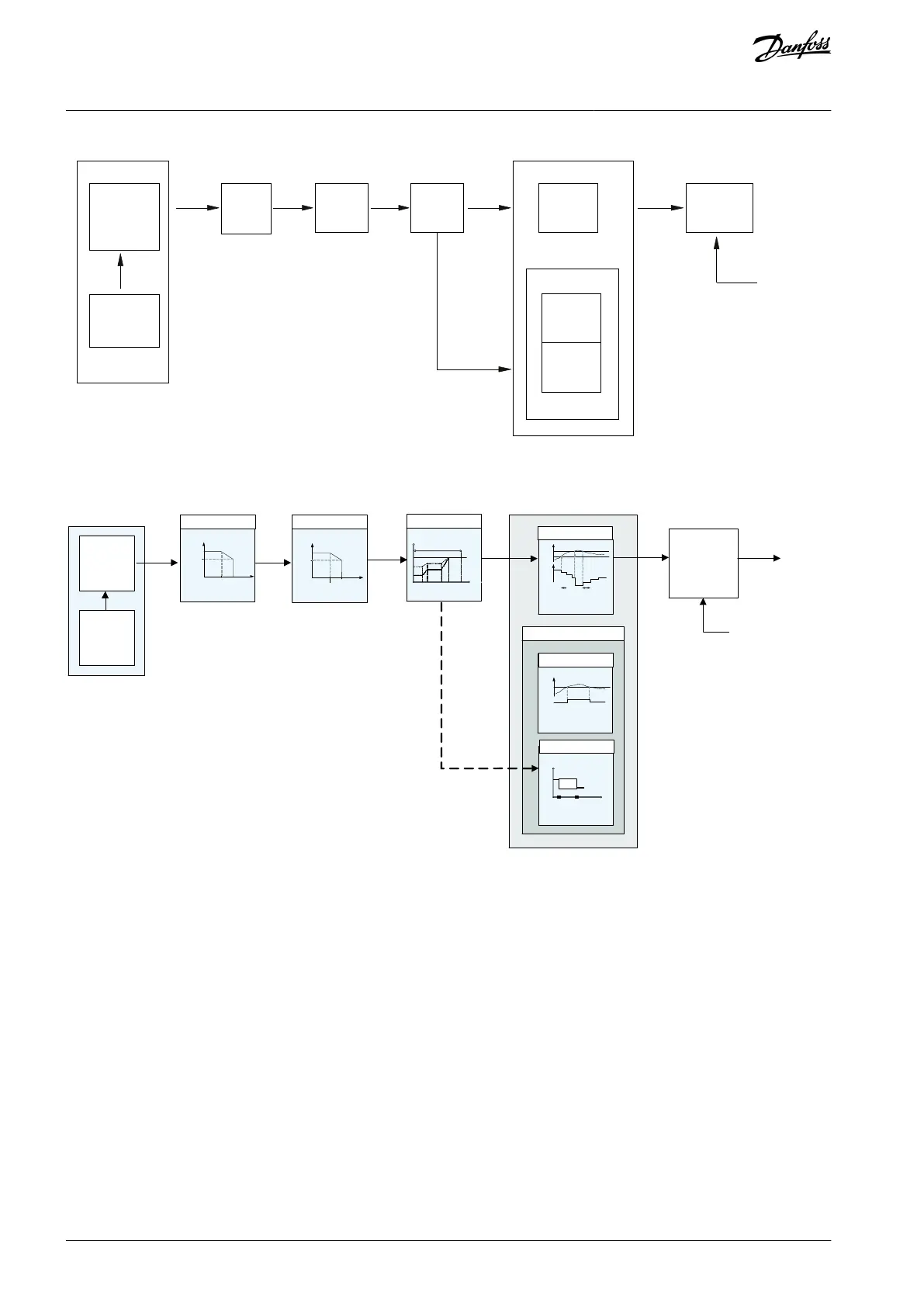
Ramp
PWM
PWM (T)
PWM (f)
Protection
flag
Illustration 24: Automatic Derating Function Block
Protection flag
(drop to f
Illustration 25: Interrelationship Between the Automatic Derating Contributions
The switching frequency is rst derated due to motor current, followed by DC-link voltage, motor frequency, and then temperature.
If multiple deratings occur on the same iteration, the resulting switching frequency would be the same as though only the most
signicant derating occurred by itself (the deratings are not cumulative). Each of these functions is presented in the following sec-
tions.
6.1.9.2 Sine-wave Filter Fixed Mode
When using sine-wave lters, it is important to operate the lters within a safe range of switching frequencies. If the switching fre-
quency is too low, the current through the lter rises, increasing the temperature with risk of damage to the lter.
During programming of the drive, it is possible to select an option for setting a minimum limit for the switching frequency. This
xed-mode function prevents the swithcing frequencies from being too low.
AJ300847815559en-000101 / 130R033740 | Danfoss A/S © 2020.09
Product Features
VLT® AQUA Drive FC 202
Design Guide
 Loading...


