EasyManuals Logo
Home>Danfoss>DC Drives>VLT AQUA FC 202

Danfoss VLT AQUA FC 202 Design Guide

Danfoss VLT AQUA FC 202
218 pages
To Next Page IconTo Next Page
To Previous Page IconTo Previous Page
Page #123 background imageLoading...
Page #123 background image
1
Minimum 16 mm
2
(6 AWG)
2
Equalizing cable
10.5.2 Wiring to Control Terminals
N O T I C E
KEEP CONTROL CABLES AS SHORT AS POSSIBLE AND SEPARATE THEM FROM HIGH-POWER CABLES TO MINIMIZE INTERFER-
ENCE.
e30bd546.12
10 mm
(0.4 in)
12 13 18 19 27
29 32 33
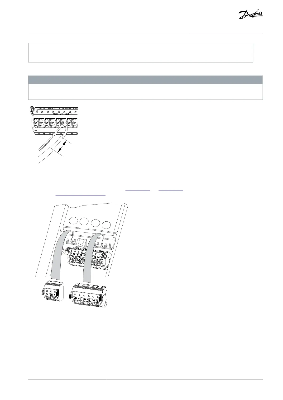
Illustration 68: Connecting Control Wires
10.5.3 Control Terminal Types
Find the location of the removable drive connectors in Illustration 69 and Illustration 70. Terminal functions and default settings are
summarized in 10.5.4 Terminal Descriptions.
e30bf144.10
Illustration 69: Control Terminal Locations
AJ300847815559en-000101 / 130R0337 | 123Danfoss A/S © 2020.09
Electrical Installation
Considerations
VLT® AQUA Drive FC 202
Design Guide

Table of Contents

Other manuals for Danfoss VLT AQUA FC 202

Questions and Answers:

Question and Answer IconNeed help?

Do you have a question about the Danfoss VLT AQUA FC 202 and is the answer not in the manual?

Danfoss VLT AQUA FC 202 Specifications

General IconGeneral
BrandDanfoss
ModelVLT AQUA FC 202
CategoryDC Drives
LanguageEnglish

Related product manuals