•
•
1
Values are measured 1 m (3.28 ft) from the unit.
2
Details, see separate design guide VLT AQUA DriveFC 202 90–710 kW
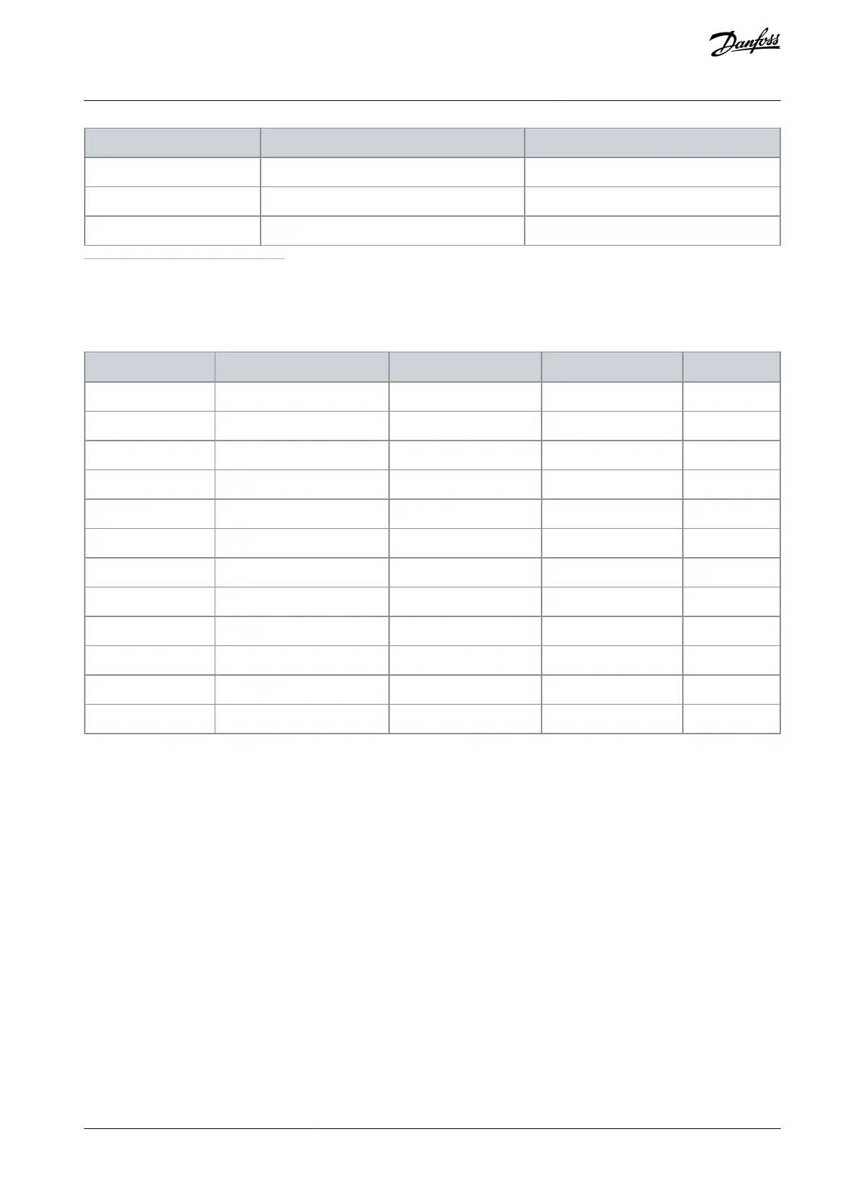
Drives are equipped with fans, which contribute to the airow in enclosures and surroundings.
Table 90: Air Flow Through the Drive
10.14 dU/dt Conditions
To avoid damage to motors without phase insulation paper or other insulation reinforcement designed for operation of the drive,
install a VLT® dU/dt lter MCC 102 or a VLT® Sine-wave Filter MCC 101 on the output of the drive.
When a transistor in the inverter bridge switches, the voltage across the motor increases by a dU/dt ratio depending on:
Motor inductance.
Motor cable (type, cross-section, length, shielded, unshielded).
The natural induction causes an overshoot voltage peak in the motor voltage before it stabilizes. The level depends on the voltage
in the DC link. Switching on the IGBTs causes peak voltage on the motor terminals. The rise time and the peak voltage aect the
service life of the motor. If the peak voltage is too high, motors without phase coil insulation can be adversely aected over time.
With short motor cables (a few meters), the rise time and peak voltage are lower. The rise time and peak voltage increase with cable
length.
The drive complies with IEC 60034-25 and IEC 60034-17 for motor design.
AJ300847815559en-000101 / 130R0337 | 145Danfoss A/S © 2020.09
Electrical Installation
Considerations
VLT® AQUA Drive FC 202
Design Guide
 Loading...


