•
•
•
•
•
-
-
•
-
-
-
•
•
11 Basic Operating Principles
11.1 Introduction
This chapter provides an overview of the primary assemblies and circuitry of a Danfoss VLT® drive. It describes the internal electrical
and signal processing functions. A description of the internal control structure is also included.
11.2 Drive Controls
A drive is an electronic controller that supplies a regulated amount of AC power to a 3-phase inductive motor. By supplying variable
frequency and voltage to the motor, the drive varies the motor speed or maintains a constant speed as the load on the motor
changes. Also, the drive can stop and start a motor without the mechanical stress associated with a line start.
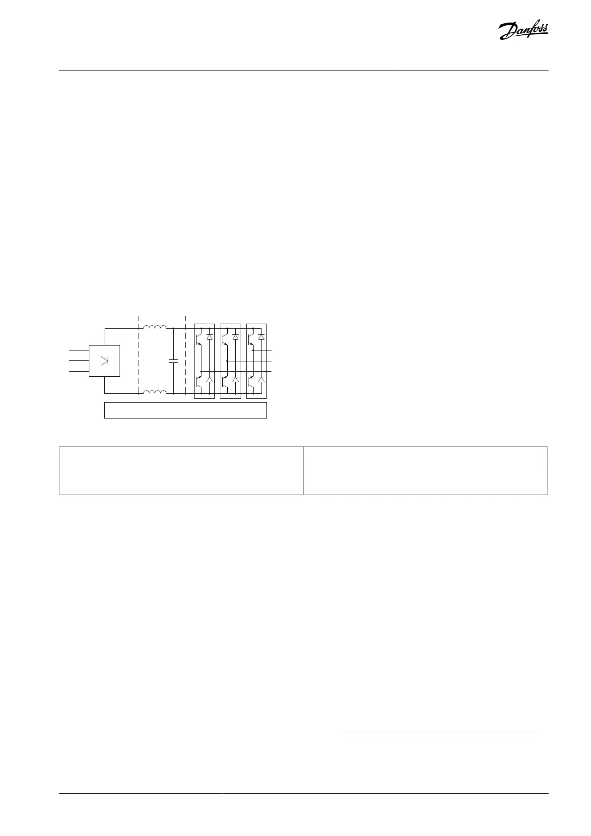
In its basic form, the drive can be divided into 4 main areas:
A rectier consisting of SCRs or diodes that convert 3-phase AC voltage to pulsating DC voltage.
A DC link consisting of inductors and their capacitor banks that stabilize the pulsating DC voltage.
An inverter using IGBTs to convert the DC voltage to variable voltage and variable frequency AC.
A control area consisting of software that runs the hardware to produce the variable voltage that controls and regulates the AC
motor.
L1
L2
L3
U
V
W
1 2 3
e30bf777.11
4
Illustration 84: Internal Processing
11.2.1 Control Principle
The control structure is a software process that controls the motor based on user-dened references, for example RPM, and whether
feedback is used or not (closed loop/open loop). The operator denes the control by selecting the conguration mode.
The control structures are as follows:
Open-loop control structure:
Speed (RPM).
Torque (Nm).
Closed-loop control structure:
Speed (RPM).
Torque (Nm).
Process (user-dened units, for example, ft, lpm, psi, %, and bar).
User inputs/references
The drive uses an input source (also called reference) to control and regulate the motor. The drive receives this input either:
Manually via the LCP. This method is referred to as local (hand on).
Remotely via analog/digital inputs and various serial interfaces (RS485, USB, or an optional eldbus). This method is referred to
as remote (auto on) and is the default input setting. See more details in 11.2.2 Local (Hand On) and Remote (Auto On) Control.
11.2.2 Local (Hand On) and Remote (Auto On) Control
Active reference refers to the active input source. The active reference is congured via parameters. For more information, refer to
the product-specic Programming Guide.
AJ300847815559en-000101 / 130R0337 | 159Danfoss A/S © 2020.09
Basic Operating Principles
VLT® AQUA Drive FC 202
Design Guide
 Loading...


