EasyManuals Logo
Home>Danfoss>DC Drives>VLT AQUA FC 202

Danfoss VLT AQUA FC 202 Design Guide

Danfoss VLT AQUA FC 202
218 pages
To Next Page IconTo Next Page
To Previous Page IconTo Previous Page
Page #118 background imageLoading...
Page #118 background image
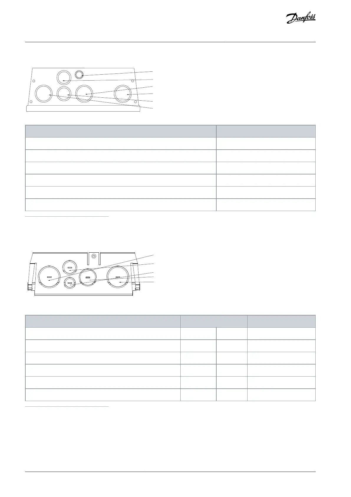
10.4.3.9 Entry Holes, Enclosure Size B1, IP55 Threaded Gland Holes
[6]
[5]
[3]
[2]
[4]
[1]
e30bb669.10
Table 55: Dimensions of Entry Holes for Enclosure Size B1, IP55 Threaded Gland Holes
Hole number and recommended use
Metric thread size
1) Mains
M32
2) Motor
M32
3) Brake/loadsharing
M32
4) Control cable
M25
5) Control cable
M25
6) Control cable
22.5 mm
(1)
1
Knockout hole
10.4.3.10 Entry Holes, Enclosure Size B2, IP21
[1]
[4]
[5]
[3]
[2]
e30bb660.11
Table 56: Dimensions of Entry Holes for Enclosure Size B2, IP21
Hole number and recommended use
Dimensions
(1)
Nearest metric
UL [in]
[mm]
1) Mains
1 1/4
44.2
M40
2) Motor
1 1/4
44.2
M40
3) Brake/loadsharing
1
34.7
M32
4) Control cable
3/4
28.4
M25
5) Control cable
1/2
22.5
M20
1
Tolerance ±0.2 mm.
AJ300847815559en-000101 / 130R0337118 | Danfoss A/S © 2020.09
Electrical Installation
Considerations
VLT® AQUA Drive FC 202
Design Guide

Table of Contents

Other manuals for Danfoss VLT AQUA FC 202

Questions and Answers:

Question and Answer IconNeed help?

Do you have a question about the Danfoss VLT AQUA FC 202 and is the answer not in the manual?

Danfoss VLT AQUA FC 202 Specifications

General IconGeneral
BrandDanfoss
ModelVLT AQUA FC 202
CategoryDC Drives
LanguageEnglish

Related product manuals