28Service Guide: EFI Fiery Central integrated server
Replacing parts
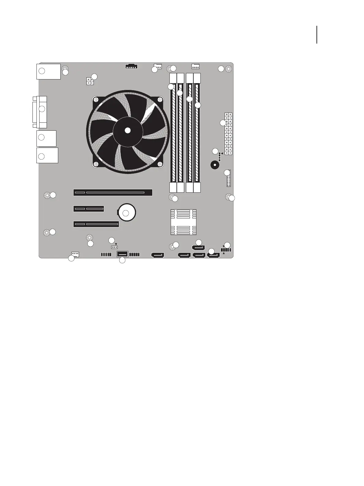
Figure 12: Motherboard
To remove boards and cables from the motherboard
1 Shut down and open the FC integrated server (see page 18).
To access the motherboard, you must remove the left side panel.
2 Remove all boards installed in slots on the motherboard.
Note the location of the slot where each board resides so that you can reinstall the board in the same slot later.
1 Type A USB2.0 ports and
network ports
7 Battery (XBT1) 13 CPU fan power (CPU FAN) 19 SATA_6G_0, DVD drive
data connection
2 Monitor (DVI) port 8 UIB cable (J27) 14 Front panel fan (REAR
FAN)
20 SATA_6G_1, Hard disk
drive data connection
3 Type A USB3.0 ports 9 DIMM0 (A1) 15 Speaker (J83) 21 Clear CMOS Jumper (J4)
4 Crossover Ethernet port/
Type A USB 3.0 ports (x2)
10 DIMM1 (A0) 16 Motherboard power (PS
connector)
MH Mounting holes
5 CPU power (J18) 11 DIMM2 (B1) 17 Front panel USB3.0 ports
(J24)
6 CPU cooling assembly 12 DIMM3 (B0) 18 Power and Rest (J15)
Note: Arrows indicate positions for inserting cable and jumper connections.
1
2
3
4
5
6
7
8
10
11
20
13
14
15
16
17
18
19
21
MH
MH
MH
MH
MH
MH
MH
MH
MH
12
9
 Loading...