EasyManuals Logo
Home>FlexRadio>Transceiver>Signature FLEX-6000 Series

FlexRadio Signature FLEX-6000 Series User Manual

FlexRadio Signature FLEX-6000 Series
222 pages
To Next Page IconTo Next Page
To Previous Page IconTo Previous Page
Page #15 background imageLoading...
Page #15 background image
FLEX-6000 Signature Series Maestro User Guide
Copyright 2024 FlexRadio, Inc. All Rights Reserved. | Page 6
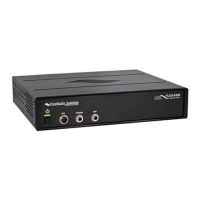
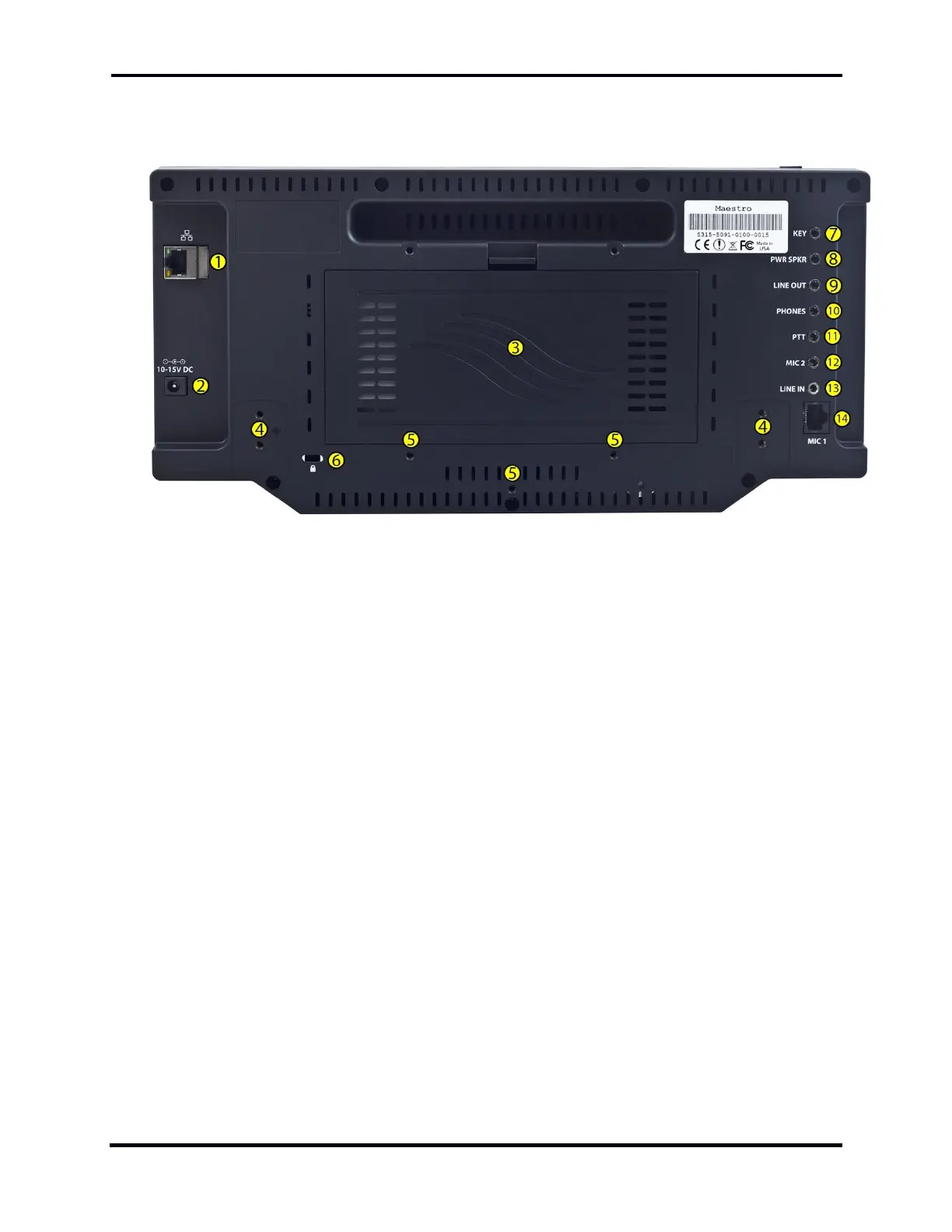
3.3.2 Maestro “A” and “B” Rear Panel Layout
The components of the Maestro A” and “B” back panel are:
1. Wired Ethernet port
2. External power port
3. Battery compartment
4. Tilt leg mounting points
5. Fixed leg mounting points
6. Physical security point
7. Morse key socket
8. Powered speakers socket
9. Line Out socket
10. Headphones socket
11. Push-To-Talk socket
12. Microphone 2 socket
13. Line In socket
14. Microphone 1 socket

Table of Contents

Questions and Answers:

Question and Answer IconNeed help?

Do you have a question about the FlexRadio Signature FLEX-6000 Series and is the answer not in the manual?

FlexRadio Signature FLEX-6000 Series Specifications

General IconGeneral
BrandFlexRadio
ModelSignature FLEX-6000 Series
CategoryTransceiver
LanguageEnglish

Related product manuals