Garmin G950 Pilot’s Guide for the Pilatus PC-6
190-00870-02 Rev. A86
SYSTEM
OVERVIEW
FLIGHT
INSTRUMENTS
EIS
AUDIO PANEL
& CNS
FLIGHT
MANAGEMENT
HAZARD
AVOIDANCE
AFCS
ADDITIONAL
FEATURES
APPENDICESINDEX
SYSTEM
OVERVIEW
FLIGHT
INSTRUMENTS
EIS
AUDIO PANEL
& CNS
FLIGHT
MANAGEMENT
HAZARD
AVOIDANCE
AFCS
ADDITIONAL
FEATURES
APPENDICESINDEX
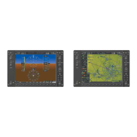
3.2 SYSTEM DISPLAY
NOTE: Refer to the Pilot’s Operating Handbook (POH) for limitations.
The System Display (Figure 3-4) is accessed by pressing the SYSTEM Softkey. The instruments presented here,
in addition to the gauges and trim slide bars, are presented into two categories: Oil (pressure and temperature)
and Electrical (currents and voltages).
Accessing the EIS System Display:
1) Press the ENGINE Softkey.
2) Press the SYSTEM Softkey.
3) To return to the default Engine Display, press the ENGINE or BACK Softkey.
1
Torque Gauge
(TRQ PSI)
Displays engine torque in pounds/square inch (lb/in
2
)
2
Interstage Turbine
Temperature Gauge
(ITT °C)
Displays Interstage Turbine Temperature (ITT) in degrees Celsius (°C) When
the engine is not running, ‘OFF’ is annunciated above the ITT readout; this
changes to ‘STRT’ upon engine start. No annunciation is shown when the
engine is running normally
3
Propeller Speed Gauge
(NP RPM)
Displays propeller speed in revolutions per minute (rpm)
4
Generator Speed Gauge
(NG %)
Displays gas generator speed as a percentage
5
Oil Pressure
(PRES PSI)
Displays engine oil pressure in pounds per square inch (psi)
6
Oil Temperature
(TEMP °C)
Displays engine oil temperature in °C
7
Ammeter
(GEN A, BAT A)
Displays DC current in amperes (A) for the generator (GEN); Alternate Power
(ALT) is not used
8
Voltmeter
(GEN V, BAT V)
Displays DC bus voltages
9
Aileron and Rudder Trim
Bars (AIL, RUD)
Aileron and rudder trim are indicated with pointers along slide bars; the
green bars indicate takeoff trim positions
10
Flap Position Indicator
(FLAPS)
Flap deflection is indicated with a pointer along a slide bar; takeoff flap
position is indicated with a green bar
11
Elevator Trim Bar
(ELEV)
Elevator trim is indicated with a pointer along a slide bar; takeoff trim position
is indicated with a green bar and T/O label
 Loading...