B30 Patient Monitor
11-4
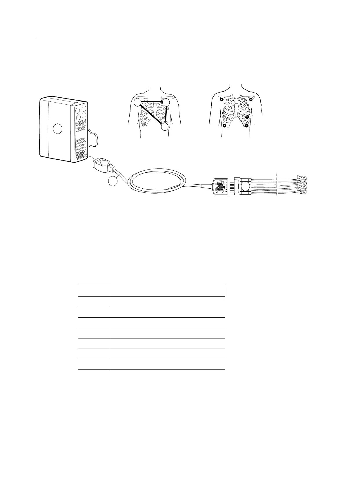
Patient connection
NOTE: Keep the ECG cable, lead set and connectors dry. Avoid excessive use of liquids
when cleaning the cables and connectors.
Figure 11-5 Example of the ECG setup with E-PSM(P)W module
(1) E-PSMW or E-PSMPW module
(2) ECG trunk cable, or 3-lead ECG cable with integrated leadwires
(3) 3 or 5 leadwire set
ECG electrodes (pre-gelled electrodes are recommended). Check the expiration data.
NOTE: For a comprehensive list of accessories, see the “Supplies and Accessories“ catalog.
Lead measurement
The following table lists the electrodes needed to measure different ECG leads:
Lead Electrodes needed
I R/RA, L/LA + F/LL or N/RL
II R/RA, F/LL + L/LA or N/RL
III LL/LA, F/LL + R/RA or N/RL
aVR N/RL, R/RA, L/LA, F/LL
aVL N/RL, R/RA, L/LA, F/LL
aVF N/RL, R/RA, L/LA, F/LL
V5 N/RL, R/RA, L/LA, F/LL, C5
L
L
R
L
R
A
I
I
I
I
I
I
L
A
R
L
R
A
L
A
2
LEAD I
L
E
A
D
I
I
I
L
E
A
D
I
I
L/ LAR/RA
F/ LL
1
3
R=RED (I EC)
RA=WHITE (AAMI)
L=YELL OW (IEC)
LA =BLACK (A AMI)
R=RED (IEC)
RA =W HITE (AAMI)
L=YELLOW (IE C)
LA=BL ACK (A AMI)
C=WHITE (IEC)
V=BROWN (AAMI )
F=GREEN (IEC)
LL=RED (AAMI)
F=GREEN (IEC)
LL=RED (AAMI)
N=BLACK (I EC)
RL =GR EEN (AAMI)

 Loading...


