5 IVUS Rev 1 Option
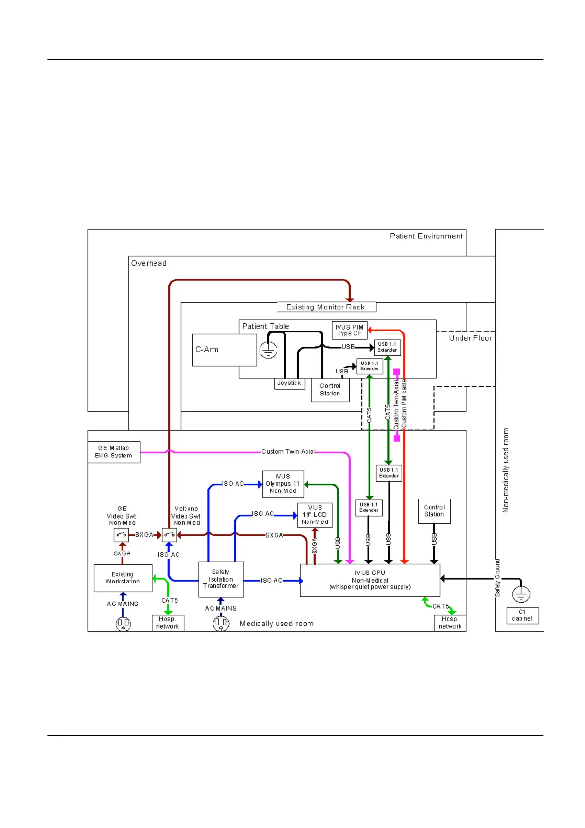
5.1 Wiring Diagram
The connection cables between the IVUS Control Room and Procedures Room components run
in a dedicated under floor conduit (see Section 5.2).
A GND wire between the C1 cabinet and the IVUS CPU runs in the underfloor conduit prepared
for the Control Booth cables between Equipment Room and Control Room.
Illustration 6-13:
Innova 2100-IQ, 3100/3100-IQ, 4100/4100-IQ Cardiovascular Imaging System Pre-Installation Manual
GE Healthcare Direction 5160944-13-1EN, Revision 2
Chapter 6 Electrical Connections 183
 Loading...