18.4.4 Run the cable Set Group 4
18.4.4.1 If no extended cables required (24 meters standard length)
1.
Lay down the cable set of the 3–Monitor or 4–Monitor suspension.
2.
Place a
pulling wire
in the duct between monitor suspension and technical area.
3. Link the
pulling wire
to the cable set, pull the cable set through the duct.
4.
Adjust the cable length at suspension level in order and chack that the suspension bridge is
free to move.
5. Unlink the
pulling wire
.
NOTE: Depending on local regulations, it can be required to put power cables in dedicated
ducts.
18.4.4.2 If cable extension required (24 meters standard too short)
1. Fix the connection box to the wall as shown on the reservation plan.
2. Lay down the cable set of the 3–Monitor or 4–Monitor suspension.
3. Place a
pulling wire
in the duct between monitor suspension and connection box.
4. Link the
pulling wire
to the cable set, pull the cable set through the duct.
5. Adjust the cable length at suspension level in order and check that the suspension bridge is
free to move.
6. Unlink the
pulling wire
and connect the cables to the connection box.
7.
Plug the extended cables
to the connection box and place cables in the duct between
connection box and technical area.
NOTE: It can be required to put power cables in dedicated ducts.
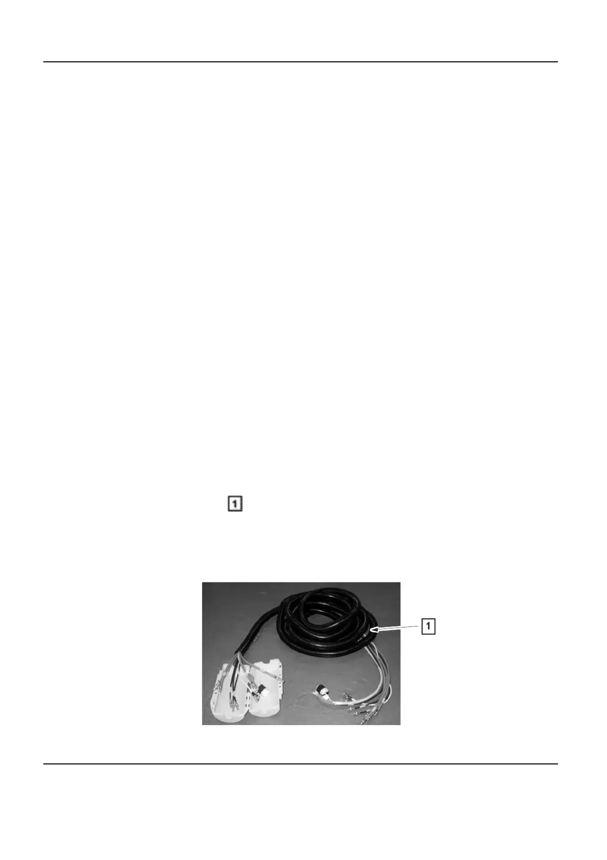
Illustration 6-32:
Innova 2100-IQ, 3100/3100-IQ, 4100/4100-IQ Cardiovascular Imaging System Pre-Installation Manual
GE Healthcare Direction 5160944-13-1EN, Revision 2
220 18 PIST0017 - System Cable Routing
 Loading...