Preparing for a Biopsy
LOGIQ V2/LOGIQ V1 – User Guide 5-29
Direction 5610736-100 Rev. 9
Displaying the Guidezone (continued)
NOTE: You can display the biopsy guideline on the CFM image in
simultaneous mode. Select the Show Biopsy Mark on CFM
simultaneous Mode preset in the Utility -> System -> System
Image -> Biopsy Guide screen.
The biopsy guidezone represents a path of the needle. The dots
which make up the guidezones is the depth readout where:
• Yellow represent 1 cm increments.
• Red represents 5 cm increments.
The display should be carefully monitored during a biopsy for
any needle deviation from the center line or guidezone.
The Biopsy Guidezone adjusts along with image adjustments,
such as image inversion/rotations, zoom and depth changes.
The needle may vary from the center line or guidezone for
various reasons:
• Needle barrel to needle clearance or strength.
• Bracket manufacturing tolerance.
• Needle deflection due to tissue resistance.
• Needle size chosen. Thinner needles may deflect more.
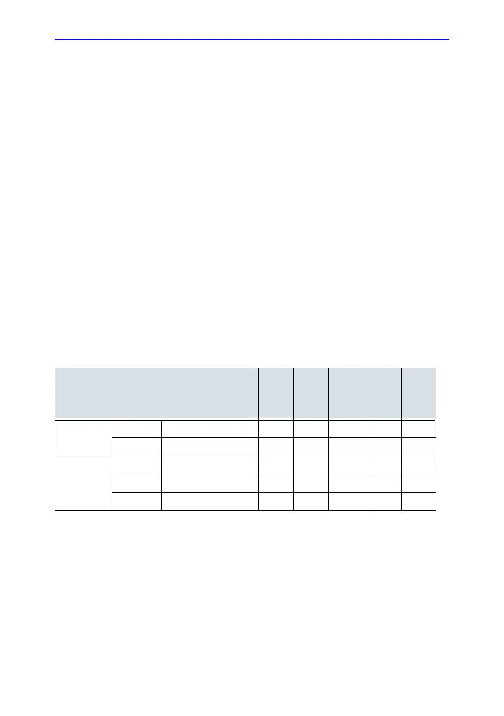
Table 5-13: Biopsy Guide Availability
Biopsy Guide
E8C-RS
L6-12-RS
3Sc-RS
4C-RS
12L-RS
Fixed Angle E8C_TR5 Biopsy Depths (cm) 15.3
E8C_RU Biopsy Angle (degree) 90
Multi-Angle MBX1 Biopsy Depths (cm) 1.5 4.2 4.0 1.5
MBX2 Biopsy Depths (cm) 2.5 5.7 6.0 2.5
MBX3 Biopsy Depths (cm) 3.5 8.2 10.0 3.5

 Loading...


