CHAPTER 4: PROGRAMMING S4 ALARMS/CONTROL
PQM POWER QUALITY METER – INSTRUCTION MANUAL 4–55
• PULSE INPUT 1 DELAY: This setpoint can be used to allow a time delay before the
assigned relay will energize after the
PULSE INPUT 1 LEVEL has been equaled or
exceeded.
• PULSE INPUT 2 RELAY: See
PULSE INPUT 1 RELAY description above and replace all
references to PULSE INPUT 1 with PULSE INPUT 2.
• PULSE INPUT 2 LEVEL: See
PULSE INPUT 1 RELAY description above and replace all
references to PULSE INPUT 1 with PULSE INPUT 2.
• PULSE INPUT 2 DELAY: See
PULSE INPUT 1 RELAY description above and replace all
references to PULSE INPUT 1 with PULSE INPUT 2.
• PULSE INPUT 3 RELAY: See
PULSE INPUT 1 RELAY description above and replace all
references to PULSE INPUT 1 with PULSE INPUT 3.
• PULSE INPUT 3 LEVEL: See
PULSE INPUT 1 RELAY description above and replace all
references to PULSE INPUT 1 with PULSE INPUT 3.
• PULSE INPUT 3 DELAY: See
PULSE INPUT 1 RELAY description above and replace all
references to PULSE INPUT 1 with PULSE INPUT 3.
• PULSE INPUT 4 RELAY: See
PULSE INPUT 1 RELAY description above and replace all
references to PULSE INPUT 1 with PULSE INPUT 4.
• PULSE INPUT 4 LEVEL: See
PULSE INPUT 1 RELAY description above and replace all
references to PULSE INPUT 1 with PULSE INPUT 4.
• PULSE INPUT 4 DELAY: See
PULSE INPUT 1 RELAY description above and replace all
references to PULSE INPUT 1 with PULSE INPUT 4.
• TOTALIZED PULSES RELAY: A relay can be selected to operate based upon a Total
Pulse Input Count as configured in the PQM. Selecting
ALARM will cause the alarm
relay to activate and display an alarm message whenever a pulse count level equals
or exceeds the selected level. Selecting AUX1, AUX2, or AUX3 will cause the
appropriate auxiliary relay to activate but no message will be displayed. The AUX1,
AUX2, and AUX3 selections are intended for process control.
• TOTALIZED PULSES LEVEL: See
PULSE INPUT 1 LEVEL description above and replace
all references to PULSE INPUT 1 with TOTALIZED PULSES.
• TOTALIZED PULSES DELAY: See
PULSE INPUT 1 DELAY description above and replace
all references to PULSE INPUT 1 with TOTALIZED PULSES.
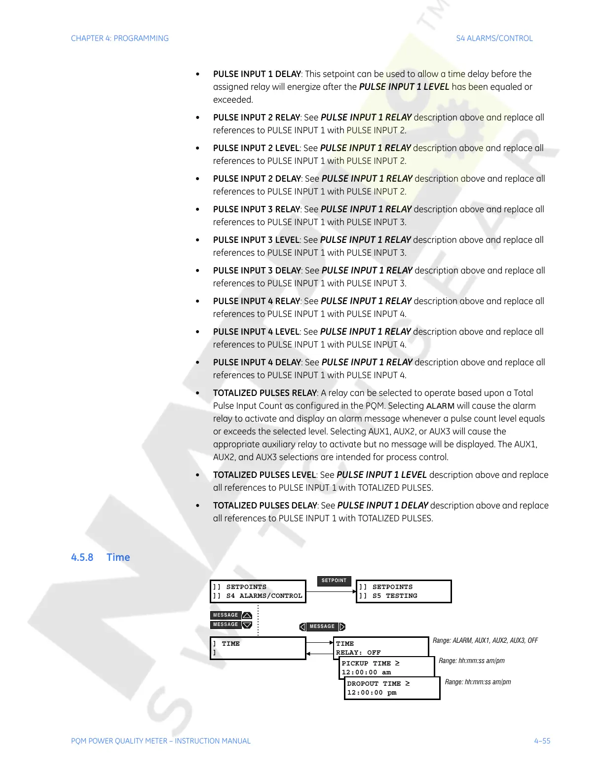
4.5.8 Time
]] SETPOINTS
]] S4 ALARMS/CONTROL
] TIME
]
TIME
RELAY: OFF
PICKUP TIME
≥
≥≥
≥
12:00:00 am
DROPOUT TIME
≥
≥≥
≥
12:00:00 pm
]] SETPOINTS
]] S5 TESTING
SETPOINT
Range: ALARM, AUX1, AUX2, AUX3, OFF
Range: hh:mm:ss am/pm
Range: hh:mm:ss am/pm
MESSAGE
MESSAGE
MESSAGE
Courtesy of NationalSwitchgear.com

 Loading...


