2–18 PQM POWER QUALITY METER – INSTRUCTION MANUAL
ELECTRICAL CHAPTER 2: INSTALLATION
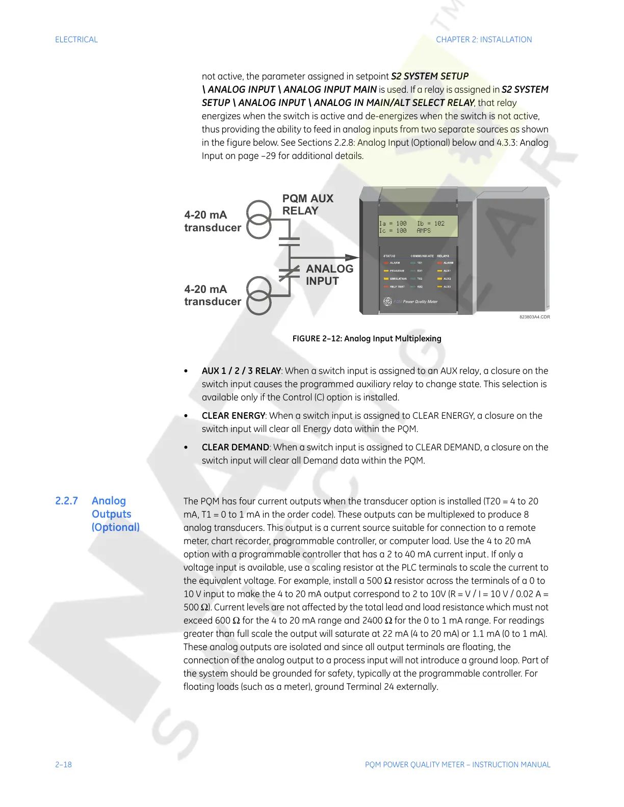
not active, the parameter assigned in setpoint S2 SYSTEM SETUP
\ ANALOG INPUT \ ANALOG INPUT MAIN
is used. If a relay is assigned in S2 SYSTEM
SETUP \ ANALOG INPUT \ ANALOG IN MAIN/ALT SELECT RELAY
, that relay
energizes when the switch is active and de-energizes when the switch is not active,
thus providing the ability to feed in analog inputs from two separate sources as shown
in the figure below. See Sections 2.2.8: Analog Input (Optional) below and 4.3.3: Analog
Input on page –29 for additional details.
FIGURE 2–12: Analog Input Multiplexing
• AUX 1 / 2 / 3 RELAY: When a switch input is assigned to an AUX relay, a closure on the
switch input causes the programmed auxiliary relay to change state. This selection is
available only if the Control (C) option is installed.
• CLEAR ENERGY: When a switch input is assigned to CLEAR ENERGY, a closure on the
switch input will clear all Energy data within the PQM.
• CLEAR DEMAND: When a switch input is assigned to CLEAR DEMAND, a closure on the
switch input will clear all Demand data within the PQM.
2.2.7 Analog
Outputs
(Optional)
The PQM has four current outputs when the transducer option is installed (T20 = 4 to 20
mA, T1 = 0 to 1 mA in the order code). These outputs can be multiplexed to produce 8
analog transducers. This output is a current source suitable for connection to a remote
meter, chart recorder, programmable controller, or computer load. Use the 4 to 20 mA
option with a programmable controller that has a 2 to 40 mA current input. If only a
voltage input is available, use a scaling resistor at the PLC terminals to scale the current to
the equivalent voltage. For example, install a 500 Ω resistor across the terminals of a 0 to
10 V input to make the 4 to 20 mA output correspond to 2 to 10V (R = V / I = 10 V / 0.02 A =
500 Ω). Current levels are not affected by the total lead and load resistance which must not
exceed 600 Ω for the 4 to 20 mA range and 2400 Ω for the 0 to 1 mA range. For readings
greater than full scale the output will saturate at 22 mA (4 to 20 mA) or 1.1 mA (0 to 1 mA).
These analog outputs are isolated and since all output terminals are floating, the
connection of the analog output to a process input will not introduce a ground loop. Part of
the system should be grounded for safety, typically at the programmable controller. For
floating loads (such as a meter), ground Terminal 24 externally.
823803A4.CD
PQM AUX
RELAY
ANALOG
INPUT
4-20 mA
transducer
4-20 mA
transducer
Courtesy of NationalSwitchgear.com

 Loading...


