CHAPTER 2: INSTALLATION ELECTRICAL
PQM POWER QUALITY METER – INSTRUCTION MANUAL 2–19
The outputs for these transducers can be selected from any of the measured parameters
in the PQM. The choice of output is selected in the
S2 SYSTEM SETUP \ ANALOG OUTPUT 1-4 setpoints group. See Section 4.3.2: Analog
Outputs on page –24 for a list of available parameters. Each analog output can be
assigned two parameters: a main parameter and an alternate parameter. Under normal
operating conditions, the main parameter will appear at the output terminals. To select the
alternate parameter, one of the switch inputs must be assigned to SELECT ANALOG OUT
and the switch input must be closed (assuming normally closed activation). By opening
and closing the switch input, two analog output parameters can be multiplexed on one
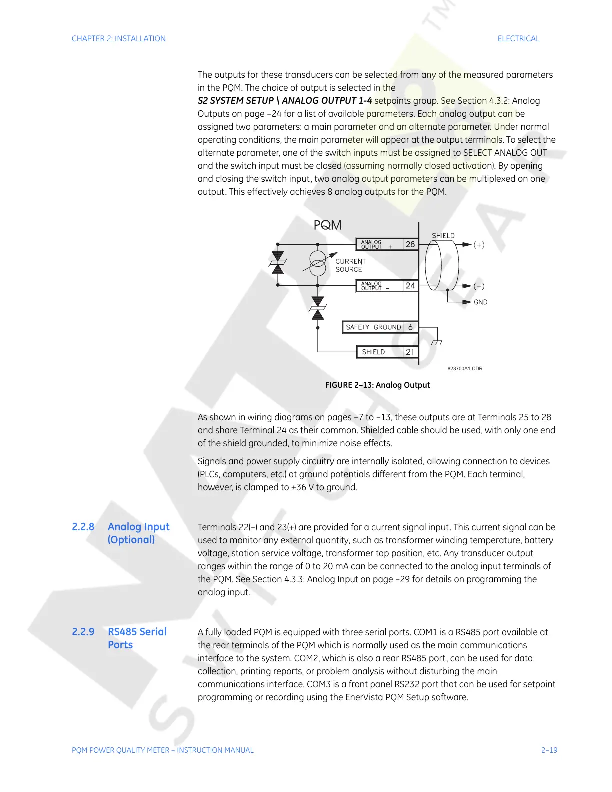
output. This effectively achieves 8 analog outputs for the PQM.
FIGURE 2–13: Analog Output
As shown in wiring diagrams on pages –7 to –13, these outputs are at Terminals 25 to 28
and share Terminal 24 as their common. Shielded cable should be used, with only one end
of the shield grounded, to minimize noise effects.
Signals and power supply circuitry are internally isolated, allowing connection to devices
(PLCs, computers, etc.) at ground potentials different from the PQM. Each terminal,
however, is clamped to ±36 V to ground.
2.2.8 Analog Input
(Optional)
Terminals 22(–) and 23(+) are provided for a current signal input. This current signal can be
used to monitor any external quantity, such as transformer winding temperature, battery
voltage, station service voltage, transformer tap position, etc. Any transducer output
ranges within the range of 0 to 20 mA can be connected to the analog input terminals of
the PQM. See Section 4.3.3: Analog Input on page –29 for details on programming the
analog input.
2.2.9 RS485 Serial
Ports
A fully loaded PQM is equipped with three serial ports. COM1 is a RS485 port available at
the rear terminals of the PQM which is normally used as the main communications
interface to the system. COM2, which is also a rear RS485 port, can be used for data
collection, printing reports, or problem analysis without disturbing the main
communications interface. COM3 is a front panel RS232 port that can be used for setpoint
programming or recording using the EnerVista PQM Setup software.
823700A1.CDR
Courtesy of NationalSwitchgear.com

 Loading...


