CHAPTER 5: MONITORING A1 METERING
PQM POWER QUALITY METER – INSTRUCTION MANUAL 5–3
5.2 A1 Metering
5.2.1 Current
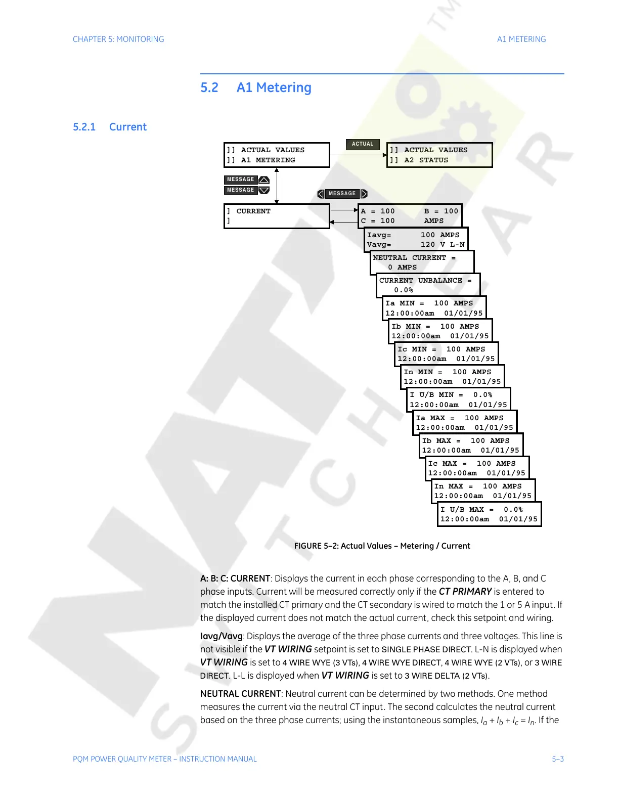
FIGURE 5–2: Actual Values – Metering / Current
A: B: C: CURRENT: Displays the current in each phase corresponding to the A, B, and C
phase inputs. Current will be measured correctly only if the
CT PRIMARY is entered to
match the installed CT primary and the CT secondary is wired to match the 1 or 5 A input. If
the displayed current does not match the actual current, check this setpoint and wiring.
Iavg/Vavg: Displays the average of the three phase currents and three voltages. This line is
not visible if the
VT WIRING setpoint is set to SINGLE PHASE DIRECT. L-N is displayed when
VT WIRING is set to 4 WIRE WYE (3 VTs), 4 WIRE WYE DIRECT, 4 WIRE WYE (2 VTs), or 3 WIRE
DIRECT
. L-L is displayed when VT WIRING is set to 3 WIRE DELTA (2 VTs).
NEUTRAL CURRENT: Neutral current can be determined by two methods. One method
measures the current via the neutral CT input. The second calculates the neutral current
based on the three phase currents; using the instantaneous samples, I
a
+ I
b
+ I
c
= I
n
. If the
]] ACTUAL VALUES
]] A1 METERING
] CURRENT
]
A = 100 B = 100
C = 100 AMPS
Iavg= 100 AMPS
Vavg= 120 V L-N
NEUTRAL CURRENT =
0 AMPS
CURRENT UNBALANCE =
0.0%
]] ACTUAL VALUES
]] A2 STATUS
ACTUAL
Ia MIN = 100 AMPS
12:00:00am 01/01/95
Ib MIN = 100 AMPS
12:00:00am 01/01/95
Ic MIN = 100 AMPS
12:00:00am 01/01/95
In MIN = 100 AMPS
12:00:00am 01/01/95
I U/B MIN = 0.0%
12:00:00am 01/01/95
Ia MAX = 100 AMPS
12:00:00am 01/01/95
Ib MAX = 100 AMPS
12:00:00am 01/01/95
Ic MAX = 100 AMPS
12:00:00am 01/01/95
In MAX = 100 AMPS
12:00:00am 01/01/95
I U/B MAX = 0.0%
12:00:00am 01/01/95
MESSAGE
MESSAGE
MESSAGE
Courtesy of NationalSwitchgear.com

 Loading...


