8–4 PQM POWER QUALITY METER – INSTRUCTION MANUAL
DNP 3.0 PROTOCOL CHAPTER 8: DNP COMMUNICATIONS
8.1.2 Implementation
Table
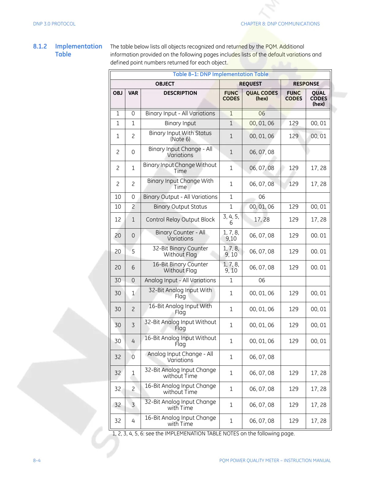
The table below lists all objects recognized and returned by the PQM. Additional
information provided on the following pages includes lists of the default variations and
defined point numbers returned for each object.
Table 8–1: DNP Implementation Table
OBJECT REQUEST RESPONSE
OBJ VAR DESCRIPTION FUNC
CODES
QUAL CODES
(hex)
FUNC
CODES
QUAL
CODES
(hex)
1 0 Binary Input - All Variations 1 06
1 1 Binary Input 1 00, 01, 06 129 00, 01
12
Binary Input With Status
(Note 6)
1 00, 01, 06 129 00, 01
20
Binary Input Change - All
Variations
1 06, 07, 08
21
Binary Input Change Without
Time
1 06, 07, 08 129 17, 28
22
Binary Input Change With
Time
1 06, 07, 08 129 17, 28
10 0 Binary Output - All Variations 1 06
10 2 Binary Output Status 1 00, 01, 06 129 00, 01
12 1 Control Relay Output Block
3, 4, 5,
6
17, 28 129 17, 28
20 0
Binary Counter - All
Variations
1, 7, 8,
9,10
06, 07, 08 129 00. 01
20 5
32-Bit Binary Counter
Without Flag
1, 7, 8,
9, 10
06, 07, 08 129 00. 01
20 6
16-Bit Binary Counter
Without Flag
1, 7, 8,
9, 10
06, 07, 08 129 00. 01
30 0 Analog Input - All Variations 1 06
30 1
32-Bit Analog Input With
Flag
1 00, 01, 06 129 00, 01
30 2
16-Bit Analog Input With
Flag
1 00, 01, 06 129 00, 01
30 3
32-Bit Analog Input Without
Flag
1 00, 01, 06 129 00, 01
30 4
16-Bit Analog Input Without
Flag
1 00, 01, 06 129 00, 01
32 0
Analog Input Change - All
Variations
1 06, 07, 08
32 1
32-Bit Analog Input Change
without Time
1 06, 07, 08 129 17, 28
32 2
16-Bit Analog Input Change
without Time
1 06, 07, 08 129 17, 28
32 3
32-Bit Analog Input Change
with Time
1 06, 07, 08 129 17, 28
32 4
16-Bit Analog Input Change
with Time
1 06, 07, 08 129 17, 28
1, 2, 3, 4, 5, 6: see the IMPLEMENATION TABLE NOTES on the following page.
Courtesy of NationalSwitchgear.com

 Loading...


