CHAPTER 8: DNP COMMUNICATIONS DNP 3.0 PROTOCOL
PQM POWER QUALITY METER – INSTRUCTION MANUAL 8–11
8.1.7 Point List For
Analog Input/
Output
Change
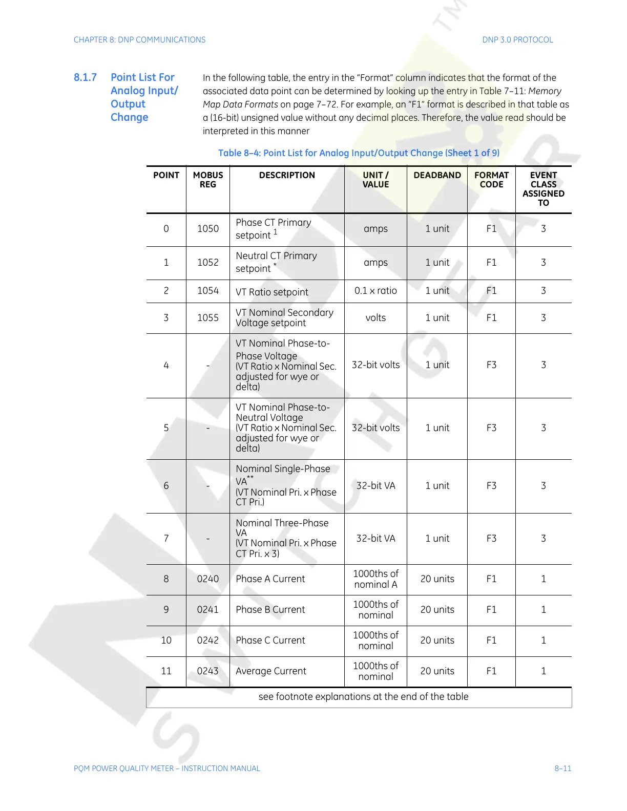
In the following table, the entry in the “Format” column indicates that the format of the
associated data point can be determined by looking up the entry in Table 7–11: Memory
Map Data Formats on page 7–72. For example, an “F1” format is described in that table as
a (16-bit) unsigned value without any decimal places. Therefore, the value read should be
interpreted in this manner
Table 8–4: Point List for Analog Input/Output Change (Sheet 1 of 9)
POINT MOBUS
REG
DESCRIPTION UNIT /
VALUE
DEADBAND FORMAT
CODE
EVENT
CLASS
ASSIGNED
TO
01050
Phase CT Primary
setpoint
1
amps 1 unit F1 3
11052
Neutral CT Primary
setpoint
*
amps 1 unit F1 3
21054
VT Ratio setpoint
0.1 x ratio 1 unit F1 3
31055
VT Nominal Secondary
Voltage setpoint
volts 1 unit F1 3
4-
VT Nominal Phase-to-
Phase Voltage
(VT Ratio x Nominal Sec.
adjusted for wye or
delta)
32-bit volts 1 unit F3 3
5-
VT Nominal Phase-to-
Neutral Voltage
(VT Ratio x Nominal Sec.
adjusted for wye or
delta)
32-bit volts 1 unit F3 3
6-
Nominal Single-Phase
VA
**
(VT Nominal Pri. x Phase
CT Pri.)
32-bit VA 1 unit F3 3
7-
Nominal Three-Phase
VA
(VT Nominal Pri. x Phase
CT Pri. x 3)
32-bit VA 1 unit F3 3
8 0240 Phase A Current
1000ths of
nominal A
20 units F1 1
90241Phase B Current
1000ths of
nominal
20 units F1 1
10 0242 Phase C Current
1000ths of
nominal
20 units F1 1
11 0243 Average Current
1000ths of
nominal
20 units F1 1
see footnote explanations at the end of the table
Courtesy of NationalSwitchgear.com

 Loading...


