CHAPTER 5: MONITORING A2 STATUS
PQM POWER QUALITY METER – INSTRUCTION MANUAL 5–23
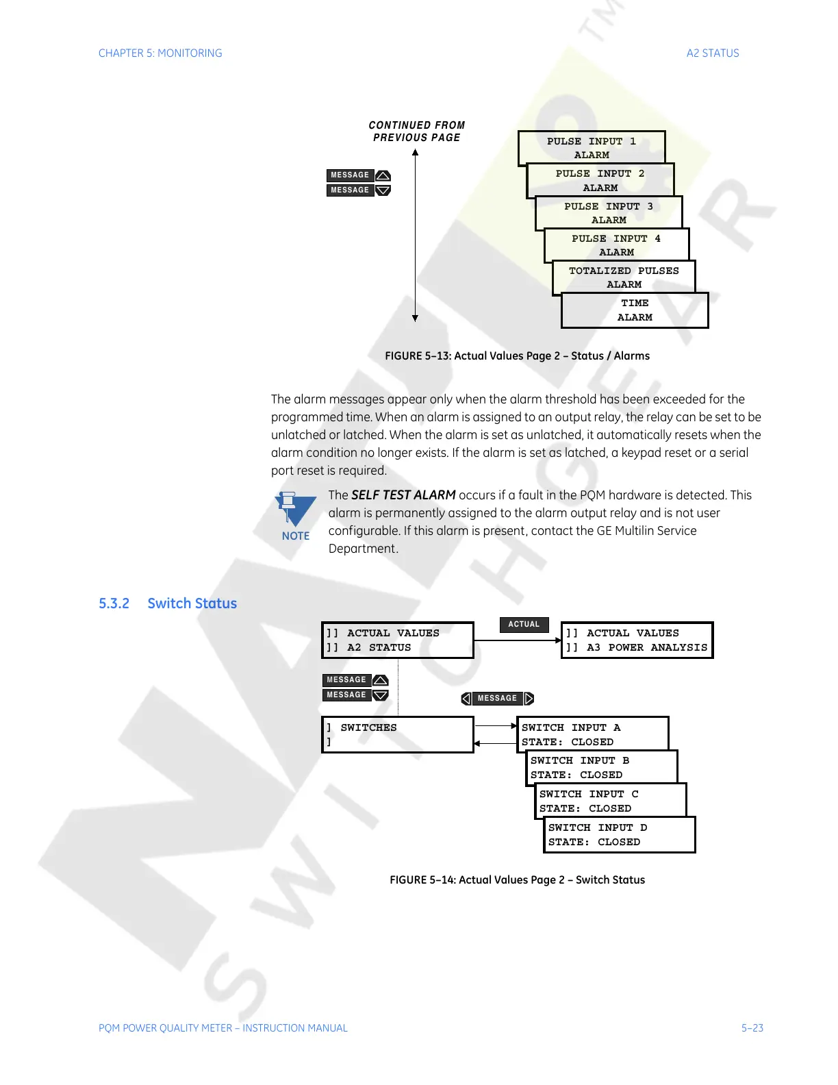
FIGURE 5–13: Actual Values Page 2 – Status / Alarms
The alarm messages appear only when the alarm threshold has been exceeded for the
programmed time. When an alarm is assigned to an output relay, the relay can be set to be
unlatched or latched. When the alarm is set as unlatched, it automatically resets when the
alarm condition no longer exists. If the alarm is set as latched, a keypad reset or a serial
port reset is required.
The
SELF TEST ALARM occurs if a fault in the PQM hardware is detected. This
alarm is permanently assigned to the alarm output relay and is not user
configurable. If this alarm is present, contact the GE Multilin Service
Department.
5.3.2 Switch Status
FIGURE 5–14: Actual Values Page 2 – Switch Status
PULSE INPUT 1
ALARM
PULSE INPUT 2
ALARM
PULSE INPUT 3
ALARM
PULSE INPUT 4
ALARM
TOTALIZED PULSES
ALARM
TIME
ALARM
MESSAGE
MESSAGE
CONTINUED FROM
PREVIOUS PAGE
NOTE
]] ACTUAL VALUES
]] A2 STATUS
] SWITCHES
]
SWITCH INPUT A
STATE: CLOSED
SWITCH INPUT B
STATE: CLOSED
SWITCH INPUT C
STATE: CLOSED
SWITCH INPUT D
STATE: CLOSED
]] ACTUAL VALUES
]] A3 POWER ANALYSIS
ACTUAL
MESSAGE
MESSAGE
MESSAGE
Courtesy of NationalSwitchgear.com

 Loading...


