7. Options
7-5
7-3 Built in PCB option
This is a built-in type option mounted on the VAT2000 control PCB.
As shown in table 7-1, there are three type of option PCBs, option
I
, option
II
and option
III
. The
VAT2000 allows mounting up to three cards, but only one of each type.
These PCB options can be easily mounted after purchasing the VAT2000 by the end user.
* The PCB option cover is required when the PCB option is mounted.
Refer to each instruction manual for details on the PCB options.
7-3-1 Option classes
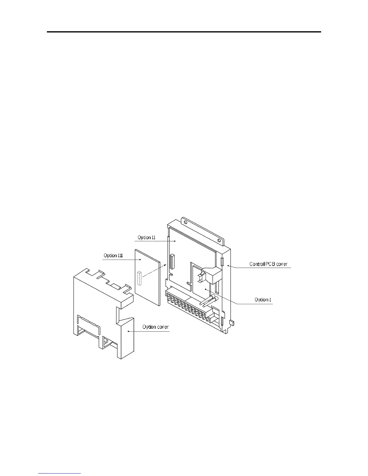
(1) Option I
This is a PCB option for speed detection during IM vector control with speed sensor and PM drive
control. The mounting position is fixed.
* The PM drive control is applicable for the standard PM motor.
(2) Option II
This is the PCB option for an analog interface, etc. The mounting position is fixed.
(3) Option III
This is the PCB option for the relay interface, etc.
Built-in PCB option mounting drawing

 Loading...


