4. Operation Panel (Keypad)
4-3
4-2 Modes and parameters
The parameters to be used differ depending of the control mode (C30-0). The parameters included are
for the V/f control (constant torque and variable torque), IM vector control (sensor-less and with sensor for
induction motors) and PM vector control (for PM motors).
These parameters are grouped into Modes and Blocks according to their functions and frequency of
usage.
4-2-1 V/f control (constant torque) and V/f control (variable torque)
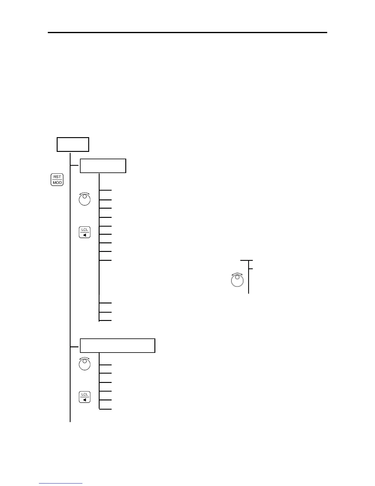
The configuration of the parameters is shown in Fig. 4-2.
Mode
Monitor mode
: Monitors (displays) the internal status.
Output frequency monitor
Frequency setting monitor
Current monitor
Voltage monitor
Sequence status
Minor fault monitor
Pattern run monitor
Multi-pump operation monitor
Extend monitor
Maintenance monitor
Automatic tuning
Hardware monitor
(d00-0~1)
(d01-0~1)
(d02-0~3)
(d03-0~3)
(d04-0~4)
(d05-0)
(d06-0~1)
(d07-0~1)
(d20-0, 2)
knob
(d21-0~3)
(d22-0)
(d30-0~1)
Fault history reference
Parameter reference,
change
•
•
Block-A Parameter Mode
: Parameters changed frequently during the normal usage
Frequency setting
Acceleration/deceleration time
Torque boost
DC brake
Custom parameters
Block B,C parameter skip
(A00-0~1)
(A01-0~1)
(A02-0~6)
(A03-0~1)
(A04-0~7)
(A05-0~2)
(Continued on next page)
Fig. 4-2 (1) Parameter configuration
knob
or
key
knob
or
key

 Loading...


