Appendix
A-9
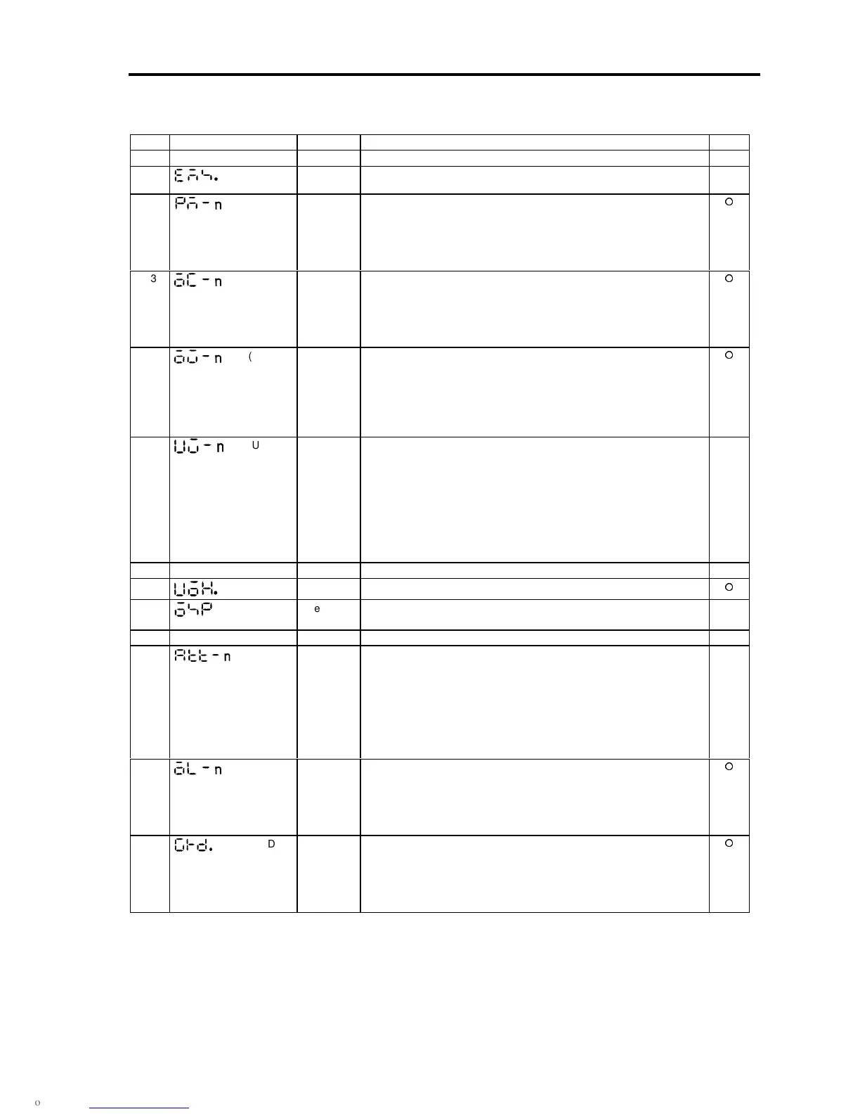
Appendix 3 Fault Codes
Code Display Fault Description Retry
0 — — — No fault No fault recorded. ×
1
(EmS)
Emergency
stop
Indicates that sequence signal EMS has been input in C00-4 = 2 (fault
output at emergency stop) mode.
×
2
(PM-n)
Power
Module
Power module fault
n: sub-code 1: during stop 2: during operation at
the set speed
3: during acceleration 4: during deceleration
5: during braking 6: during ACR
7: during pre-extension 9: during automatic tuning
3
(OC-n)
Over
current
The output has risen to or beyond 300%.
n: sub-code 1: during stop 2: during operation at
the set speed
3: during acceleration 4: during deceleration
5: during braking 6: during ACR
7: during pre-extension 9: during automatic tuning
4
(OV-n)
Over
voltage
The DC voltage has risen to or beyond the preset level. (Vdc
≥
800 or
400V)
n: sub-code 1: during stop 2: during operation at
the set speed
3: during acceleration 4: during deceleration
5: during braking 6: during ACR
7: during pre-extension 9: during automatic tuning
5
(UV-n)
Under
voltage
While the drive is running, the DC voltage has lowered to or beyond the
preset level (65% of the rating).
n: sub-code 1: during stop 2: during operation at
the set speed
3: during acceleration 4: during deceleration
5: during braking 6: during ACR
7: during pre-extension 9: during automatic tuning
At C08-0 = 2, 3 (automatic start), only the symbol displays, so the FLT
LED and terminal block FA, FB and FC contacts will not operate. EC0 to
3 will operate.
×
6 Not defined
7 Overheat The heatsink temperature has risen to or beyond 95°C.
8 Overspeed Indicates that the motor speed exceeded the overspeed setting value
(C24-0).
×
9 Not defined
A
(ATT-n)
Automatic
tuning
abnormal
completion
This indicates that the automatic tuning did not complete normally.
n: Automatic tuning step No. (when interrupted)
(1) ACR simple setting
(2) Single-phase AC measurement
(3) ACR adjustment
(9) Excitation inductance measurement
(A) Secondary resistance measurement
(B) Max. torque boost adjustment
(C) Excitation inductance fluctuation table adjustment
×
B
(OL-n)
Overload
Indicate that the output current exceeded the thermal operation time
having inverse time characteristics. The standard characteristics are
150% for one minute in respect to the motor rated current. At 155% or
more in respect to the inverter rated current, this will be 170% for 2.5
seconds.
n: Sub-code 1: Drive output overload
C
(GRD. n)
Ground The Drive has sensed a grounded conditions on the output.
n: sub-code 1: during stop 2: during operation at
the set speed
3: during acceleration 4: during deceleration
5: during braking 6: during ACR
7: during pre-extension 9: during automatic tuning

 Loading...


