8. Maintenance and Inspection
8-4
8-4 Troubleshooting with fault display
The countermeasures for when the inverter stops with a fault code display are shown in Table 8-4.
Table 8-4 Troubleshooting (1)
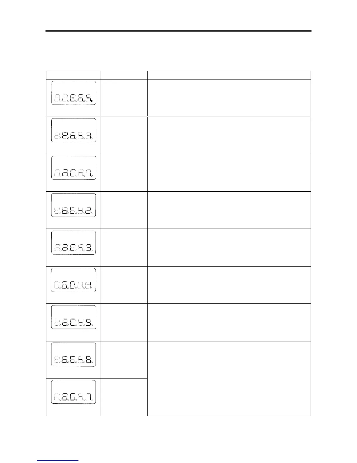
Display symbol Name Causes and countermeasures
EMS.
Emergency stop 1. The sequence input EMS has been activated.
Check the signal wiring.
2. This fault occurs when C00-4=2.
PM-1~PM-9
Power module 1. Indicates that the short circuit protection circuit activated.
2. The sub-codes and causes and countermeasures are the
same as for OC-1~9.
OC-1
Overcurrent
during stop
1. The power module in the main circuit may be broken.
OC-2
Overcurrent
during constant
speed operation
1. A sudden change in the load or short circuit may have
occurred.
Reduce the load fluctuation.
OC-3
Overcurrent
during
acceleration
1. Increase the acceleration time setting (A01-0).
2. Reduce the torque boost voltage (A02-2).
3. An excess GD
2
, short circuit or rapid fluctuation of the load
may have occurred.
OC-4
Overcurrent
during
deceleration
1. Increase the deceleration time setting (A01-1).
2. A short circuit or rapid fluctuation of the load may have
occurred.
OC-5
Overcurrent
during braking
1. Reduce the brake voltage setting (A03-0).
2. A short circuit in the load may have occurred.
OC-6
Overcurrent
during ACR
1. A short circuit in the load may have occurred.
OC-7
Overcurrent
during
pre-excitation

 Loading...


