5. Control Input / Output
5-10
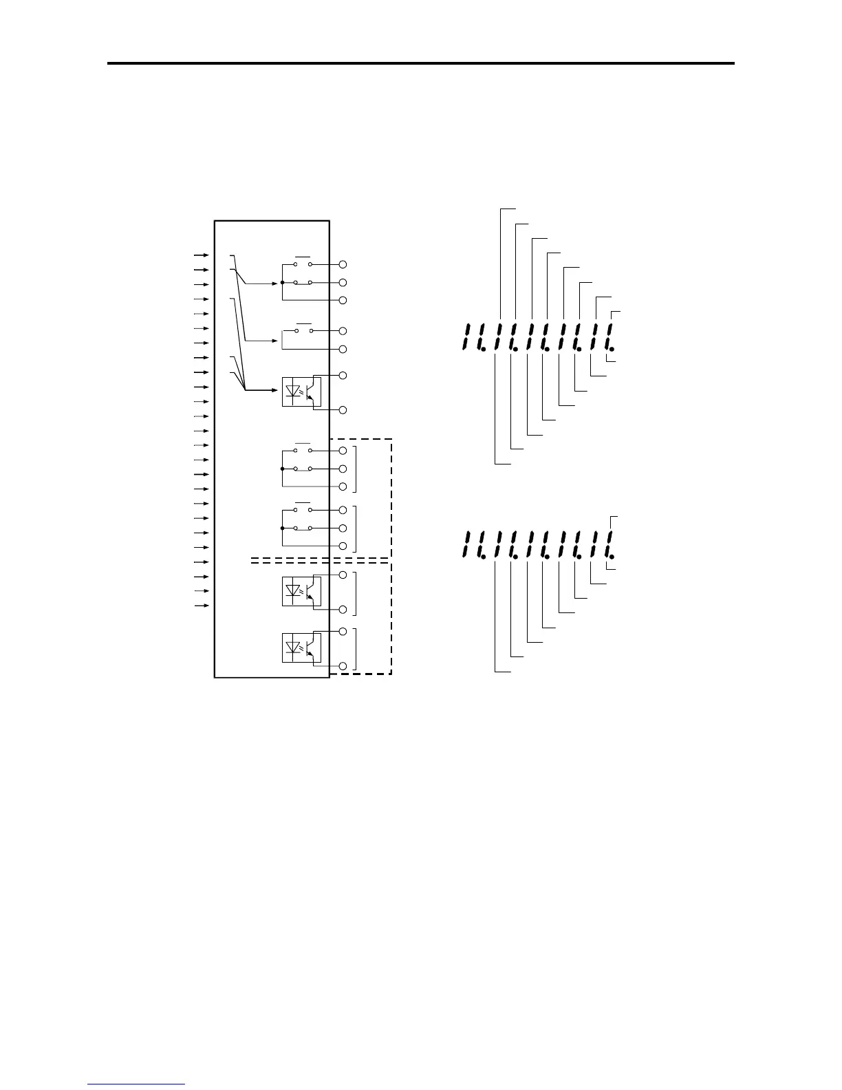
5-6-2 Sequence output terminal assignment and monitoring
The ON/OFF of the internal signals can be output to the RA-RC and PSO1 to 3-PSOE terminals as
shown in Fig. 5-5 with the parameter Nos. C13-2 to 5 and C33. The ON/OFF of each signal can be
monitored as shown in Fig. 5-6. This monitoring is executed with D04-3, 4.
Terminal
board
Internal
Signal
1
0
(Output
fixed)
C13-2=0
C13-3=3
C13-4=7
C13-5=8
2
3
4
5
6
7
8
9
10
11
12
13
14
15
RUN
FLT
MC
RDY1
RDY2
LCL
REV
IDET
ATN
SPD1
SPD2
COP
EC0
EC1
EC2
EC3
PSO
EC3
EC2
EC1
EC0
COP
SPD2
SPD1
RUN
FLT
MC
RDY1
RDY2L
LCL
(D04-3 display)
REV
IDET
ATN
PSO1-3
PSOE
U2KV23RYO Option
PSO5
PSO5
PSO4
PSO4
FA
FB
FC
RA
RC
16
17
18
19
20
21
23
22
24
ACC
DCC
AUXDV
ALM
FAN
ASW
LLMT
ZSP
ULMT
U2KV23PIO Option
ACC
ULMT
LLMT
DCC
AUXDV
ALM
FAN
ASW
ZSP
(D04-4 Display)
Fig. 5-5 Assignment of sequence output Fig. 5-6 Sequence output monitor

 Loading...


