5. Control Input / Output
5-17
(1-1) External reduction setting
The torque limit can be reduced using the signal provided from an analog input or from the serial
transmission . Either analog or serial signals can be selected by setting a parameter or from the
drive’s terminal board.
Setting
input point
Setting data Explanation
Analog drive torque limit
reduction setting
The drive torque limit (A10-3 or A11-2) may be reduced in
percentage using an analog input. For example using a
signal of 0V to +10V the limit torque is reduced from 0 to
100%.
This function is enabled when LIM1, is ON.
Analog
Analog regenerative
torque limit reduction
setting
The regenerative torque limit (A10-4, A10-5 or A11-3) may
be reduced in percentage using an analog input. For
example using a signal of 0V to +10V the limit torque is
reduced from 0 to 100%.
This function is enabled when LIM2 is ON.
Serial drive torque limit
reduction setting
A serial interface option U2KV23SL0.
The drive torque limit (A10-3, A11-2), may be reduced in a
percentage using the data 0 to 100% provided from serial
transmission.
For example using a signal of 0 to 100% the limit torque is
reduced from 0 to 100%.
This function is enabled when LIM1 is ON.
Serial
Serial regenerative
torque limit reduction
setting
A serial interface option U2KV23SL0
The regenerative torque limit (A10-4, A10-5, A11-3), may
be reduced in a percentage using the data 0 to 100%
provided from serial transmission.
For example using a signal of 0 to 100% the limit torque is
reduced from 0 to 100%.
This function is enabled when LIM2 is ON.
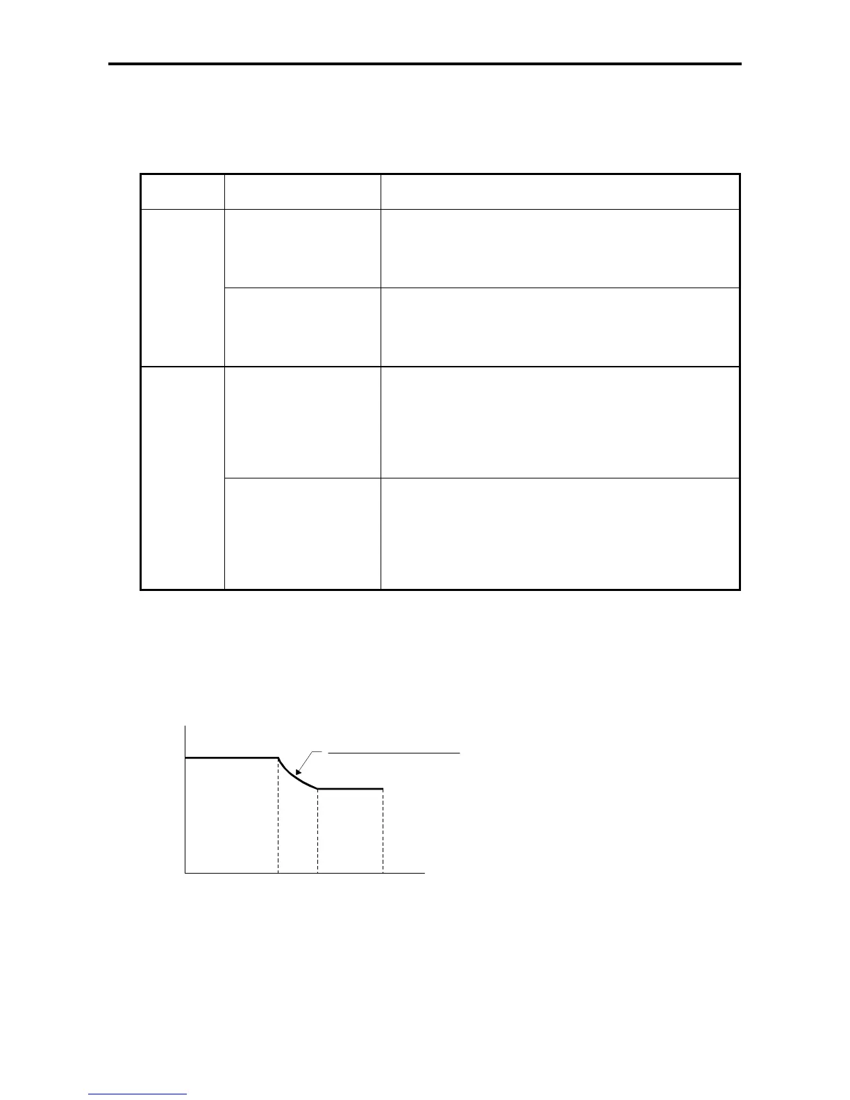
(1-2) Internal reduction setting
The torque limit may be reduced as well by setting a value lower than 100% in the parameter
“Double rating speed ratio”, B13-4. The reduction generated in the limiter function, in percentage,
is shown below, and will depend of the base speed and real speed ratio. The resultant multiplier
will reduce the limit values set in A10-3, A11-2, A10-4, A10-5 and A11-3.
KDBL : B13-4
Double rating speed ratio (%)
NFB : Speed detection (rpm)
NBASE: Base speed (rpm)
NDBL : NBASE x KDBL (rpm)
Speed (rpm)
100%
NDBL
KDBL
KDBL (%) x NBASE (rpm)
NFB (rpm)
Reduction ratio (%)
NBASE NMAX

 Loading...


