6. Control Functions and Parameter Settings
6-8
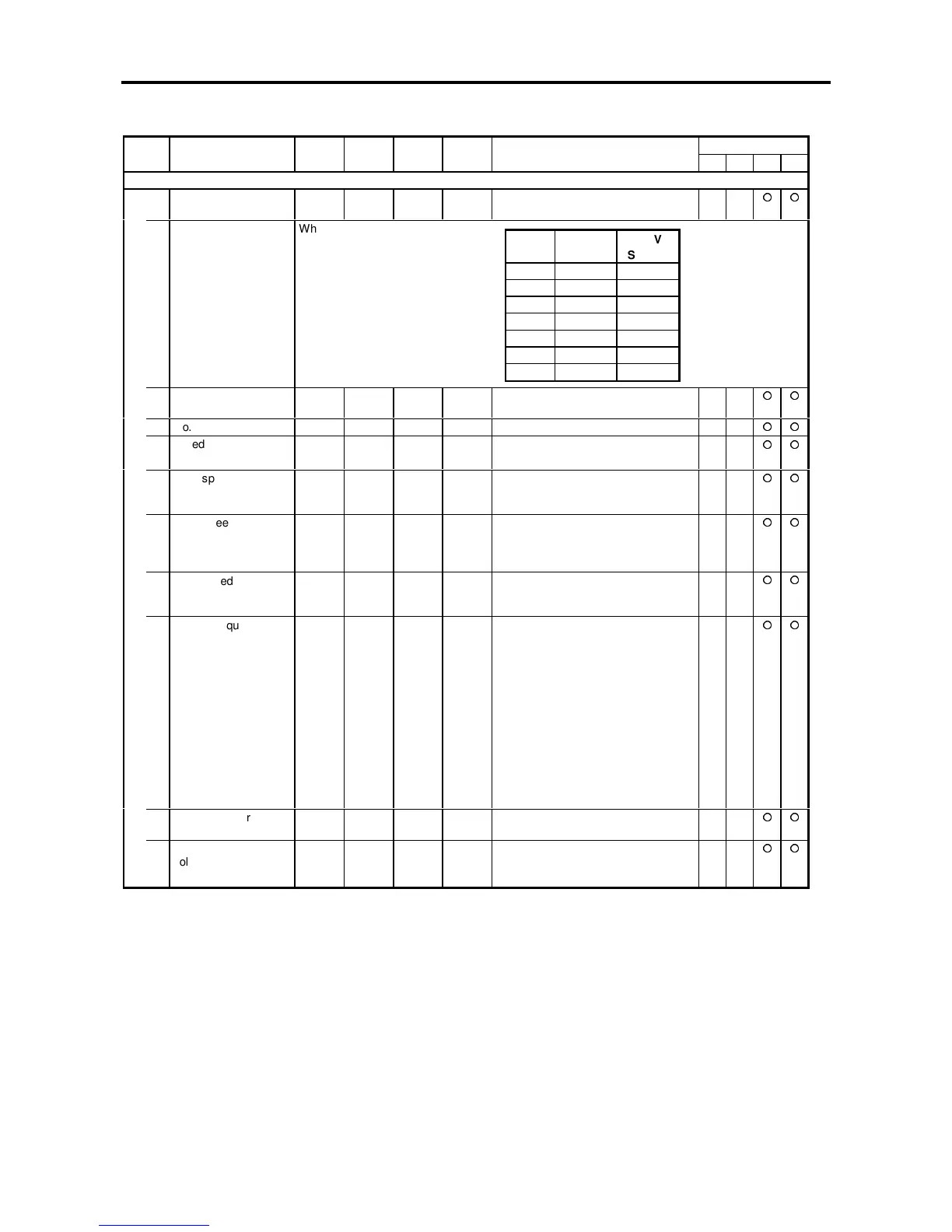
Block-B parameters (Basic function of vector control) list
ApplicationNo. Parameter Unit Default Min. Max. Function
ST V/f VEC PM
B01 – Output rating
0 Rated input voltage
setting
7. 1. 7. Select the rated input voltage from the
following table.
When this data is changed, the
output voltage data will also be
changed to the same value.
1 Motor rated output kW Inverter
rating
0.10 500.00 Motor rated power at the base speed
2 No. of motor poles Pole 4. 2. 16.
3 Rated output voltage V 200
/400.
40. 480. This is the motor rated voltage at
base speed, full load
4 Max. speed min
–1
1800. 150. 7200. This is the max. motor speed. The
maximum value is 4-times the base
speed.
5 Base speed min
–1
1800. 150. 7200. This is the motor base (rated) speed.
When the motor is controlled above
that speed, the flux during vector
control will be weakened.
6 Motor rated current A Inverter
rating
Inverter
rating
× 0.3
Inverter
rating
This is the motor current during full
load at the base speed.
7 Carrier frequency 17.0 1.0 21.0 The noise can be lowered by
changing the PWM carrier frequency
and control method, which affects to
the sound generated from the motor.
This can be changed while running.
1.0 to 15.0:
Monotone sound method (Carrier
frequency: 1.0 to 15.0kHz)
15.1 to 18.0:
Soft sound method 1 (Basic
carrier frequency: 2.1 to 5.0kHz)
18.1 to 21.0:
Soft sound method 2 (Basic
carrier frequency: 2.1 to 5.0kHz)
8 No. of encoder pulses P/R 1000. 60. 10000. This must be set in vector control with
sensor mode
9 No-load output
voltage
V 160. 20. 500. This is the voltage during no-load at
the base speed.
Adjusted by Auto-tuning
Value
200V
System
400V
System
1 200V 380V
2 200V 400V
3 200V 415V
4 220V 440V
5 220V 460V
6 220V 480V
7 230V 400V

 Loading...


