5. Control Input / Output
5-1
Chapter 5 Control Input / Output
5-1 Input / Output Terminal Function
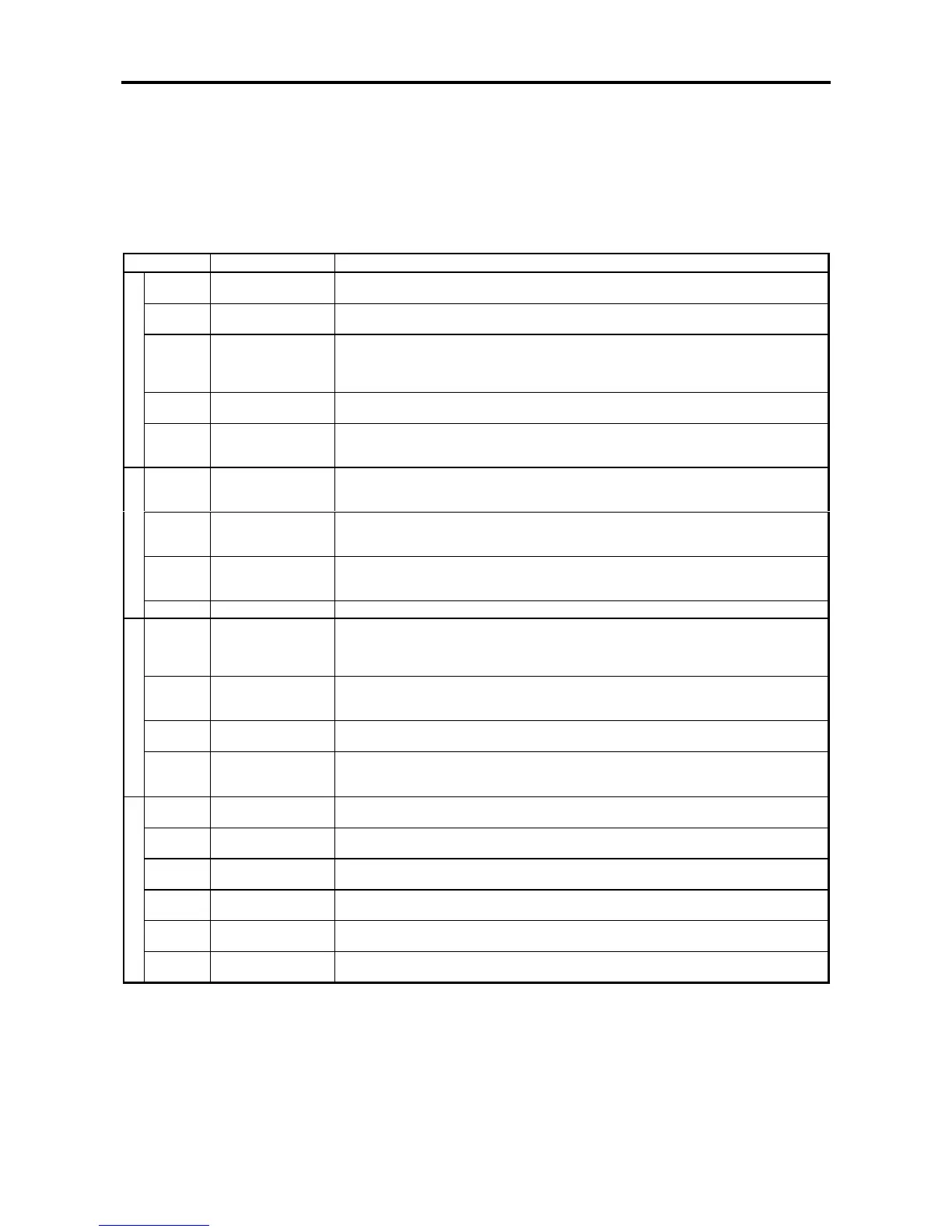
The terminal block and input/output functions related to control are shown in Tables 5-1.
Table 5-1 Terminal block functions
Symbol Name Features
RY0, RY24 Relay input common This is a common terminal for relay input signals specified below. Either sink or source logic
control can be changed with internal jumper W1.
PSI1~PSI5 Programmable input
These are programmable inputs, which can be assigned to remotely ON/OFF control any of
the sequence input functions (C03 to C06).
EMS Emergency stop
If EMS is ON while the VAT2000 is stopped, all operational commands are inhibited. If it is ON
during operation, the VAT2000 is led into a stopping sequence, either ramp down stop or
coast-to-stop selectable.
It is also possible to output this signal as a fault (FLT). (C00-4)
RESET Fault reset This reset a faulty condition. With this signal, a fault status output (FLT LED, FAULT relay
operation) is turned OFF and operation is allowed again.
Sequence input
RUN Forward run
This is a command for forward run. Either permanent or push-buttons commands for
run/reverse control can be selected. Operating command from RUN terminal is allowed in the
remote operation mode (LCL LED unlighted). (C00-0)
FSV
Voltage/frequency
setting
This is mainly used for frequency (or speed) setting input. The maximum frequency (speed)
setting is available at a 10V input. This setting is enabled when VFS of the internal relay signal
is ON. (C04-1, C07-0=2, C12-0=1)
FSI
Current/frequency
setting
This is mainly used for frequency (or speed) setting input. A maximum frequency (speed)
setting is available at a 20mA input. This setting is valid when IFS of the internal relay signal is
ON. (C04-2, C07-1=3, C12-1=1)
AUX Auxiliary input This is mainly used for frequency (or speed) setting input. A maximum frequency (speed)
setting is available at a ±10V input. This setting is valid when AUX of the internal relay signal
is ON. (C04-3, C07-2=4, C12-2=1)
Analog input
COM Analog input common This is a common terminal for FSV, FSI and AUX signals.
FM Frequency meter This is a voltage output signal for metering purpose. As default, a 10V output is available at
the maximum frequency. This output voltage can be adjusted from 0.2 to 2.0 times 10V. (Max.
output is, however, approximately 11 volts.) Internal analog signals other than output
frequency can also be output. (C13-0, C14-0)
AM Ammeter This is a voltage output signal for metering purpose. As default, an output of 5V is available for
the rated current. This output voltage adjustment of 0.2 to 2.0 times of 5V is also available.
Internal analog signals other than those of current can also be output. (C13-1, C14-1)
COM Analog output
common
This is a common terminal for the analog outputs.
Analog output
P10 FSV source This is a 10V source used when a frequency (speed) setter is connected to the FSV input
circuit.
The frequency (speed) setter to be used should be a variable resistor of 2W and 2k
Ω
.
RC, RA RUN This is a contact to be ON during operation or DC braking. Other internal ON/OFF signals can
be output with the C13-2 setting.
FC, FA, FB Fault
These contacts switch when a fault occurs (then the FLT LED lights). When a fault occurs, NO
contact FA-FC switches to ON and the NC contact FB-FC switches to OFF.
PSO1 READY (1)
This is the open collector output that turns ON at READY status.
Other internal signals can be output with the C13-3 setting.
PSO2 Current detection This is the open collector output that turns ON when the output current reaches the setting.
(C15-1) Other internal signals can be output with the C13-4 setting.
PSO3 Frequency (speed)
attainment
This is the open collector output that turns ON when the output frequency (speed) reaches the
setting. (C15-0) Other internal signals can be output with the C13-5 setting.
Sequence output
PSOE Open collector output
common
These are the common terminals for the PSO1, 2 and 3 signals.

 Loading...


